In a Machine, every component is subjected to various forces. Due to these forces acting on the machine components, there are various types of stresses are induced. Where a simple stress is defined as the internal resistance force that opposes the external force per unit area. Where the Strain is defined as the deformation per unit length. Let us understand Engineering Stress and Engineering Strain in more detail.
While designing machine elements we need to consider the Engineering stress and Engineering strain.
Engineering Stress
Let us consider a cylindrical rod of length l0 and cross-sectional area A0 subjected to a uniaxial tensile force F, as shown in the below figure.
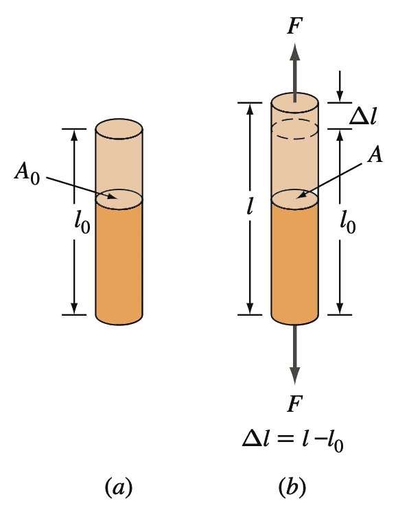
(b) Rod is subjected to a uniaxial tensile force F
By definition, the engineering stress σ on the bar is equal to the average uniaxial tensile force F on the bar divided by the original cross-sectional area A0 of the bar.
Because F is normal (perpendicular) to the area, this stress is also called the normal stress. Thus,
Engineering stress σ will be the average uniaxial tensile force by the original cross-sectional area.
σ = F / A0
The SI units for engineering stress are newtons per square meter (N/m2) or pascals (Pa),
We know 1 N/m2 = 1 Pa
The imperial units for engineering stress are pounds-force per square inch (lbf /in.2, or psi)
We know lbf means pounds-force
The conversion factors for psi to pascals are
1 psi = 6.89 × 10³ Pa
106 Pa = 1 megapascal = 1 MPa
1000 psi = 1 ksi = 6.89 MPa
Let us solve an example problem on finding the Engineering stress of an aluminum bar.
Example Problem to calculate Engineering Stress
A 2500 kg mass is hanging from a 1.25-cm-diameter bar. Calculate the normal engineering stress on the bar in megapascals (MPa).
Answer:
The load on the bar is calculated based on the gravity pull of the 2500 kg mass.
In SI units, the force on the bar is equal to the mass of the load times the acceleration of gravity g = 9.81 m/s2
F = mg = (2500 kg)(9.81 m/s2) = 24,500 N
The diameter d of the bar = 1.25 cm = 0.0125 m.
The Engineering stress σ will be the average uniaxial tensile force by the original cross-sectional area.
σ = F / A0
σ = 24,500 / (π/4)(0.0125)2
σ = 2 × 10⁸ N/m2
σ = 200 × 106 Pa
σ = 200MPa
This is how you can calculate the engineering stress for any machine component.
Engineering Strain
Let us consider a cylindrical rod of length l0 and cross-sectional area A0 subjected to a uniaxial tensile force F, as shown in the below figure.

(b) Rod is subjected to a uniaxial tensile force F
When a uniaxial tensile force is applied to a rod, such as that shown in the above figure, it causes the rod to be elongated in the direction of the force or in perpendicular to the cross-section.
Such a displacement over the full length of the bar is called a normal engineering strain.
By definition, engineering strain, which is caused by the action of a uniaxial tensile force on a metal sample, is the ratio of the change in length of the sample in the direction of the force divided by the original length of the sample considered.
Thus, the normal engineering strain for the metal bar will be the change in length of the sample (Δl) by the original length of the sample (l0)
Engineering strain ϵ (normal strain) = (l − l0) / l0
where
l0 = original length of sample
l = new length of sample after being extended by a uniaxial tensile force.
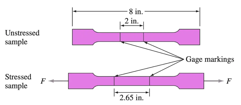
In most cases, engineering strain is determined by using a small length, usually, 2 inches, called the gage length, within a much longer, for example, 8 in., sample
The SI units for engineering strain ϵ are meters per meter (m/m)
The Imperial units for engineering strain ϵ are inches per inch (in./in.)
Thus, engineering strain has dimensionless units. In industrial practice, it is common to convert engineering strain into percent strain.
% engineering strain = engineering strain × 100%
Let us solve an example problem on finding the Engineering strain of an aluminum bar.
Example Problem to calculate Engineering Strain
A sample of commercially pure aluminum 0.500 in. wide, 0.040 in. thick, and 8 in. long that has gage markings 2.00 in. apart in the middle of the sample is strained so that the gage markings are 2.65 in. apart shown in the below figure. Calculate the normal engineering strain and the percent engineering strain that the sample undergoes.
Answer:
Engineering strian ϵ = (l − l0) / l0
ϵ = (2.65 in. − 2.00 in.) / 2.00 in.
ϵ = 0.65 in / 2.00 in
ϵ = 0.325
% elongation = 0.325 × 100%
% elongation = 32.5%
Poisson’s Ratio
A longitudinal elastic deformation of metal produces an accompanying lateral dimensional change. As shown in the below figure, a tensile stress σz produces a normal tensile strain +ϵz and lateral normal compressive strains of −ϵx and −ϵy.
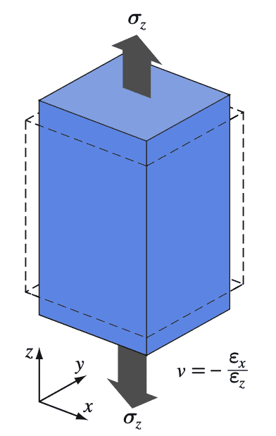
For isotropic behavior (exhibiting properties with the same values when measured along axes in all directions), ϵx and ϵy are equal. The ratio of the strain in the lateral direction to the longitudinal direction is called Poisson’s ratio.
Poisson’s ratio is represented with “v“
v = − ϵ (lateral) /ϵ (longitudinal)
v = -ϵx/ ϵz
v = – ϵy / ϵz
For ideal materials, the Poisson’s ratio v = 0.5. However, for real materials, Poisson’s ratio typically ranges from 0.25 to 0.4, with an average of about 0.3.
The below Table lists modulus of elasticity, shear modulus, and Poisson’s ratio (v) values for some of the isotropic metals and alloys.
| Material | Modulus of Elasticity 106 psi (GPa) | Shear Modulus 106 psi (GPa) | Poisson’s Ratio |
| Aluminum alloys | 10.5 (72.4) | 4.0 (27.5) | 0.31 |
| Copper | 16.0 (110) | 6.0 (41.4) | 0.33 |
| Steel (plain carbon and low-alloy) | 29.0 (200) | 11.0 (75.8) | 0.33 |
| Stainless steel (18-8) | 28.0 (193) | 9.5 (65.6) | 0.28 |
| Titanium | 17.0 (117) | 6.5 (44.8) | 0.31 |
| Tungsten | 58.0 (400) | 22.8 (157) | 0.27 |
(Isotropic materials exhibit properties with the same values when measured along axes in all directions)
Shear Stress and Shear Strain
Until now, we have discussed the elastic and plastic deformation of metals and alloys under uniaxial tensile stresses producing normal stresses and strains. Another important method by which a metal can be deformed is under the action of shear stress. The action of a simple shear stress couple (shear stresses act in pairs) on a cubic body is shown in the below figure, where a shearing force S acts over an area A.
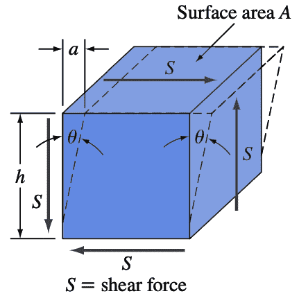
Shear Stress (τ) = Shear force (S) / Area over which shear force acts (A)
The SI units for shear stress are the same as for uniaxial normal tensile stress which is newtons per square meter (N/m2) or pascals (Pa).
Similarly, the Imperial units for shear stress are pounds-force per square inch (lbf /in.2, or psi)
The shear strain γ is defined in terms of the amount of the shear displacement “a” in the above figure divided by the distance “h” over which the shear acts, or
γ = a/h = tan θ
For pure elastic shear, the proportionality between shear and stress is
τ = Gγ
where G is the elastic modulus.
We can generalize that normal stresses and strains result in changes in length and volume of the metal while shearing stresses and strains result in changes in the shape of the metal.
True Stress and True Strain
The engineering stress is calculated by dividing the applied force F on a tensile test specimen by its original cross-sectional area A0. Since the cross-sectional area of the test specimen changes continuously if we conduct a tensile test, the engineering stress calculated is not precise as the actual stress induced in the tensile stress.
During the tensile test, the necking of the specimen happens for ductile materials. After the necking of the sample occurs, the engineering stress decreases as the strain increases, leading to maximum engineering stress in the engineering stress-strain curve. This necking is represented below.
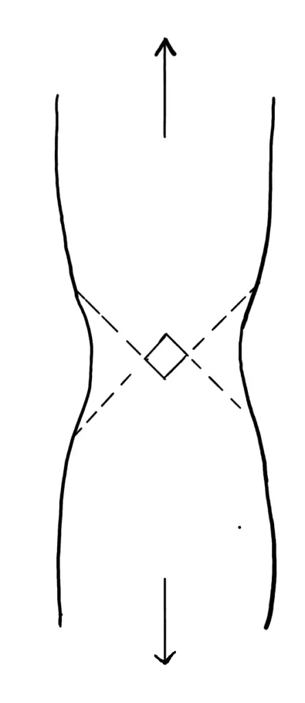
Thus, once necking begins during the tensile test, the true stress is higher than the engineering stress. We define the true stress and true strain by the following:
True stress σt = Average uniaxial force on the test sample)/ Instantaneous minimum cross-sectional area of the sample
σt = F / Ai

where l0 is the original gauge length of the sample and li is the instantaneous extended gauge length during the test.
If we assume the constant volume of the gage-length section of the test specimen during the test, then
l0A0 = li Ai
li/ l0 = A0/ Ai
ϵt = ln (li/ l0)= ln (A0/ Ai)
Below Stress-Strain Curve compares engineering stress-strain and true stress-strain relation for low carbon steel.
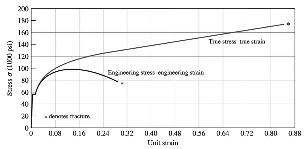
Engineering designs are not based on true stress at fracture since as soon as the yield strength is exceeded, the material starts to deform. Engineers use instead of the 0.2% offset engineering yield stress for structural designs with the proper safety factors. However, for research, sometimes the true stress-strain curves are needed.
Conclusion
We have discussed what is engineering stress and engineering strain in a detailed manner. Other related topics under stress-strain are the as follows
- Stress-strain curve detailed explination
- Principal Stresses and principal Planes
- Torsional Stress
- Bearning Stress
- Bending Stress
- Shear stress
- Stress Concentration
- Methods of Reducing Stress Concentration
Let us know what do you think about this article in the comment section below.

Leave a Reply