We have already discussed what a flywheel is and its uses. A flywheel used in machines serves as a reservoir that stores energy during the period when the supply of energy is more than the requirement and releases it during the period when the requirement of energy is more than the supply. In the case of steam engines, internal combustion engines, reciprocating compressors, and pumps, the energy is developed during one stroke and the engine is to run for the whole cycle on the energy produced during this one stroke. In the previous article we have discussed the Different stresses in a Flywheel Rim and Flywheel Arms. Let us now discuss the Design of Flywheel Arms, Shaft, Hub and Key.
Design of Flywheel Arms
The cross-section of the arms is usually elliptical with major axis as twice the minor axis, as shown in the following figure, and it is designed for the maximum bending stress.
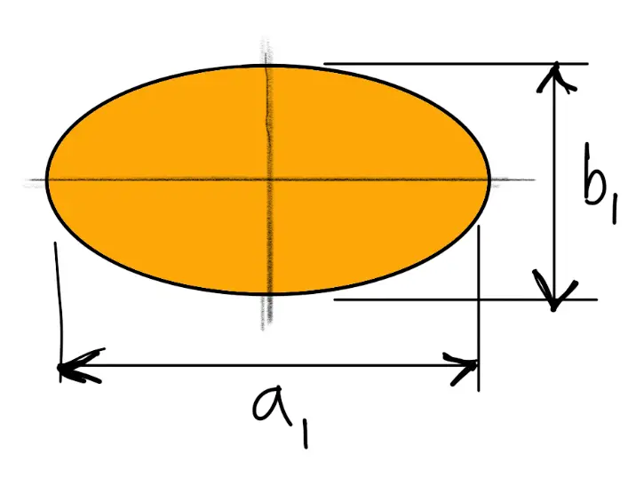
Let
a1 = Major axis
b1 = Minor axis

We know that maximum bending moment,
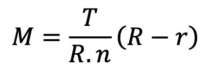
∴ Maximum bending stress,

Assuming a1 = 2 b1, the dimensions of the arms may be obtained from the above two equations.
👉 Important Notes:
- The arms of the flywheel have a taper from the hub to the rim. The taper is about 20 mm per metre length of the arm for the major axis and 10 mm per metre length for the minor axis.
- The number of arms are usually 6. Sometimes the arms may be 8, 10 or 12 for very large size flywheels.
- The arms may be curved or straight. But straight arms are easy to cast and are lighter.
- Since arms are subjected to reversal of stresses, therefore a minimum factor of safety 8 should be used. In some cases like punching machines and machines subjected to severe shock, a factor of safety 15 may be used.
- The smaller flywheels (less than 600 mm diameter) are not provided with arms. They are made web type with holes in the web to facilitate handling.
Design of Shaft, Hub and Key
The diameter of shaft for flywheel is obtained from the maximum torque transmitted. We know that the maximum torque transmitted,

where
d1 = Diameter of the shaft
τ = Allowable shear stress for the material of the shaft
The hub is designed as a hollow shaft, for the maximum torque transmitted. We know that the maximum torque transmitted,

Where
d = Outer diameter of hub
d1 = Inner diameter of hub or diameter of shaft
The diameter of hub is usually taken as twice the diameter of shaft and length from 2 to 2.5 times the shaft diameter. It is generally taken equal to width of the rim.
A standard sunk key is used for the shaft and hub. The length of key is obtained by considering the failure of key in shearing. We know that torque transmitted by shaft,

L = Length of the key
τ = Shear stress for the key material
d1 = Diameter of shaft
Let us solve an Example problem to understand the above procedure and the other parameters from the previous articles we have discussed so far on the flywheel.
Example Problem on Design of Flywheel
Problem Statement: A punching press pierces 35 holes per minute in a plate using 10 kN-m of energy per hole during each revolution. Each piercing takes 40 per cent of the time needed to make one revolution. The punch receives power through a gear reduction unit which in turn is fed by a motor driven belt pulley 800 mm diameter and turning at 210 r.p.m. Find the power of the electric motor if overall efficiency of the transmission unit is 80 per cent. Design a cast iron flywheel to be used with the punching machine for a coefficient of steadiness of 5, if the space considerations limit the maximum diameter to 1.3 m.
Allowable shear stress in the shaft material τ = 50 MPa = 50N/mm2
Allowable tensile stress for cast iron σt = 4 MPa = 4N/mm2
Density of cast iron ρ = 7200 kg/m3
Answer:
Given Data as follows:
Number of holes = 35 per min
Energy per hole = 10 kN-m = 10 000 N-m
Driven Pulley d = 800mm = 0.8m
Driven pulley speed N = 210r.p.m
Efficiency η = 80% = 0.8
Coefficient of Steadiness 1/CS = 5 or CS = 1/5 = 0.2
Maximum Diameter of Flywheel Dmax = 1.3m
Allowable shear stress in the shaft material τ = 50 MPa = 50N/mm2
Allowable tensile stress for cast iron σt = 4 MPa = 4N/mm2
Density of cast iron ρ = 7200 kg/m3
Power of the electric motor
We know that energy used for piercing holes per minute = No. of holes pierced × Energy used per hole
= 35 × 10000 = 350000 Nm/min
∴ Power needed for the electric motor,

The Power needed for the electric motor is 7.292 kW.
Design of cast iron flywheel
First of all, let us find the maximum fluctuation of energy.
Since the overall efficiency of the transmission unit is 80%, therefore total energy to be supplied during each revolution,

We know that velocity of the belt,
v = π d . N = π × 0.8 × 210 = 528m/min
∴ Net tension or pull acting on the belt

Since each piercing takes 40 per cent of the time needed to make one revolution, therefore time required to punch a hole
= 0.4 / 35 = 0.0114 min
and the distance moved by the belt during punching a hole = Velocity of the belt × Time required to punch a hole
= 528 × 0.0114 = 6.03 m
∴ Energy supplied by the belt during punching a hole, EB = Net tension × Distance travelled by belt
= 828.6 × 6.03 = 4996 N-m
Thus energy to be supplied by the flywheel for punching during each revolution or maximum fluctuation of energy,
∆E = ET – EB
∆E = 12500–4996
∆E = 7504 N-m
Mass of the Flywheel
Let us say
m = Mass of the flywheel rim.
Since space considerations limit the maximum diameter of the flywheel as 1.3 m ; therefore let us take the mean diameter of the flywheel,
D = 1.2m or R = 0.6m
We know that angular velocity

We also know that the maximum fluctuation of energy (∆E),
7504 = m.R2.ω2.CS
7504 = m (0.6)2 (22)2 0.2
7504 = 34.85 m
m = 7504/34.85
∴ m =215.3kg
Cross-sectional dimensions of the flywheel rim
Let us assume
t = Thickness of the flywheel rim in metres
b = Width of the flywheel rim in metres = 2 t
∴ Cross-sectional area of the rim A = b × t = 2t × t = 2t2
We know that mass of the flywheel rim (m),
215.3 = A × π D × ρ
215.3 = 2t2 × π × 1.2 × 7200
215.3 = 54.3 × 10³ t2
t2 = 215.3/54.3 × 103
t2 = 0.00396
t = 0.063 say 0.065 m
t = 65 mm
Thickness of the flywheel rim in metres t = 65 mm
And, the width of the flywheel rim in metres
b = 2t = 2 × 65 = 130mm
Diameter and length of hub
Let us assume
d = Diameter of the hub
d1 = Diameter of the shaft
l = Length of the hub
First of all, let us find the diameter of the shaft (d1). We know that the mean torque transmitted by the shaft,

Assuming that the maximum torque transmitted by the shaft is twice the mean torque, therefore maximum torque transmitted by the shaft,
We know that maximum torque transmitted by the shaft (Tmax),
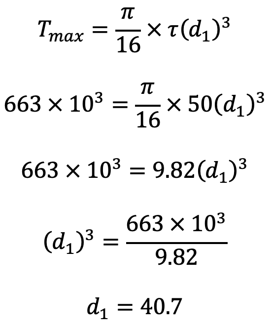
Let us say the d1 as 45mm.
The diameter of the hub (d) is made equal to twice the diameter of the shaft (d1) and length of hub ( l ) is equal to the width of the rim (b).
d = 2d1 = 2 × 45 = 90mm = 0.09m
l = b = 130mm
Cross-sectional dimensions of the elliptical cast iron arms
Let us assume
a1 = Major axis,
b1 = Minor axis = 0.5 a1
n = Number of arms = 6
We know that the maximum bending moment in the arm at the hub end, which is assumed as cantilever is given by
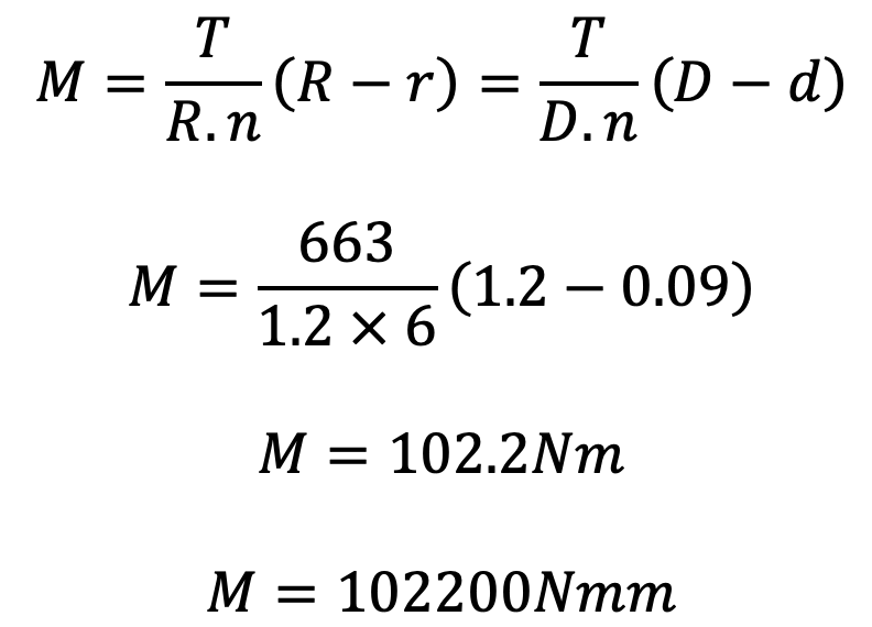
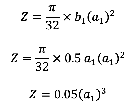
and section modulus for the cross-section of the arms,
We know that bending stress (σt),
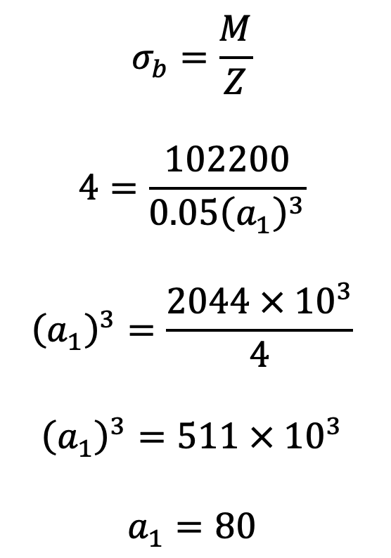
Dimensions of key
The standard dimensions of rectangular sunk key for a shaft of diameter 45 mm are as follows:
Width of key, w = 16 mm
and thickness of key = 10 mm
The length of key (L) is obtained by considering the failure of key in shearing. We know that maximum torque transmitted by the shaft (Tmax),
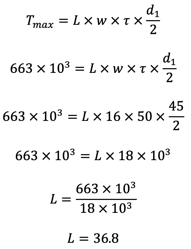
Let us say the length of key L is 38mm.
Let us now check the total stress in the rim which should not be greater than 4 MPa. We know that the velocity of the rim,

Total stress in the rim, (Refer this Article this formula)
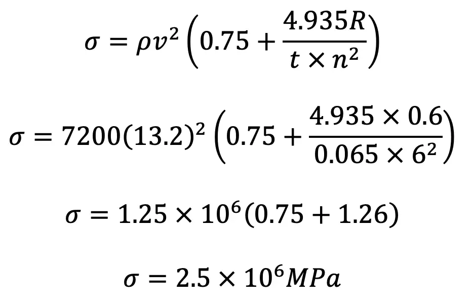
Since it is less than 4 MPa, therefore the design is safe.
This is all about the design of Flywheel Arms, rim, shaft, hub and key. Let us know what you think about this article in the comment section below.

Leave a Reply