In the previous tutorial, we have discussed the list of Material Testing Methods, in this tutorial we are going to discuss how to conduct the tensile test.

Tensile Test
The tensile test comes under the destructive test where we apply the gradually increased load up to the material to get a fracture. So a tensile test is a static test as a sub-classification.
Tensile testing is used to find the behavior of the material when it is subjected to a slowly applied tensile load up to when the material gets a fracture.
This test will be conducted on the universal testing machine. Also, known as UTM.
Universal Testing Machine
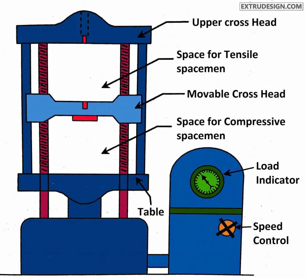
The main parts of the Universal testing machine are
- Upper cross Head
- Movable cross Head
- Table
- Load Indicator
- Speed control
- Space for tensile specimen
- Space for Compressive Specimen
Construction of Universal Testing Machine
The universal testing machine has two vertical threaded shafts where the movable crosshead will slide on these vertical Bars. the Crosshead will be constant. If it is a tensile test then the specimen will be placed in between the Crosshead and the movable head jaws, if it is a compressive test The specimen will be placed in between the movable head and the table. With the help of the loading dial indicator, we can observe how much load is applied to the specimen during the test.
We can do both the Tensile test and the compressive test on this universal testing machine.
Back to the subject of Tensile testing, We have to place the specimen in between the upper crosshead and the movable crosshead for tensile testing.
Now we have to apply the load gradually so that the movable crosshead will move downwards.
We have to slowly increase the load until the specimen gets a fracture or breaks completely.
Stress-strain diagram for the Tensile testing
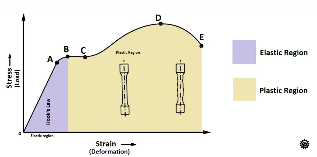
- A = Proportional limit
- B= Elastic limit
- C = Yield Point
- D = Ultimate Tensile Strength
- E = Fracture
- O-B = Elastic region
- B-E = Plastic Region
Read more about the Stress-strain diagram here!
You can see that the specimen will be able to elongate and can come back to its original shape when the load is removed up till point B since it is the elastic limit.
After the applied load crosses the elastic limit the specimen cannot regain its original shape even after removal of the load but still, it will elongate till the Point D. point D is called Ultimate tensile strength.
After the load reaches point D, the specimen starts necking (Reduction in the cross-section) due to the local extension.
Due to the necking, the load will be reduced for the final fracture. you can observe the drop in the graph from point D to point E.
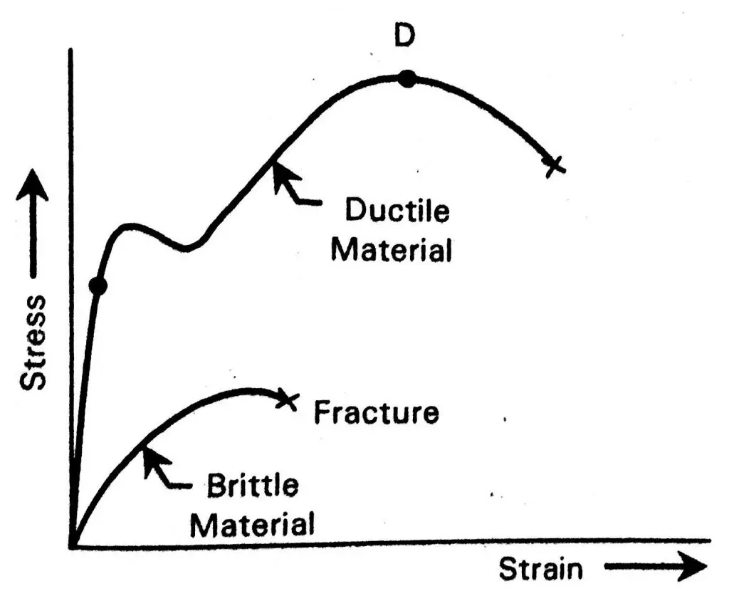
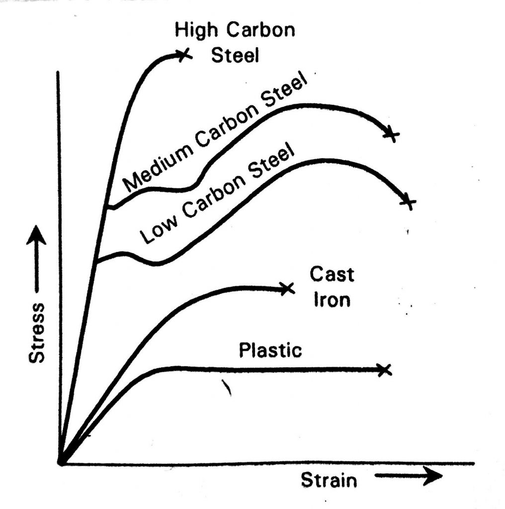
Stress-strain diagram for the different materials
a) Stress-strain diagram for Brittle material vs the Ductile material
b) Stress-strain diagram for Carbon steels, cast iron, plastic
Tensile Deformation of Ductile Metal such as Aluminium or Copper
Do you wish to understand how the ductile materials will deform under the tensile test?
The basic data on the mechanical properties of a ductile metal is obtained from a tension test, in which a suitably designed specimen is subjected to increasing axial load until it fractures. The load and elongation are measured at frequent intervals during the test and are expressed as average stress and strain according to certain equation equations that will be discussed later.
As we have already discussed that the data obtained from the tension test are generally plotted as a stress-strain diagram. Following is the image that shows a typical stress-strain curve for a metal such as aluminum or copper.
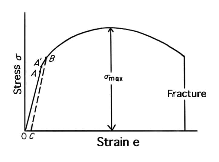
- The initial linear portion of the curve OA is the elastic regionwithin which Hooke’s law is obeyed.
- Point A is the elasticlimit, defined as the greatest stress that the metal can withstand without experiencing a permanent strain when the load is removed.
- The determination of the elastic limit is quite tedious, not at all routine, and dependent on the sensitivity of the strain-measuring instrument.
- For these reasons it is often replaced by the proportional limit, point A’. The proportional limit is the stress at which the stress-strain curve deviates from linearity.
- The slope of the stress-strain curve in this region is the modulus of elasticity.
- For engineering purposes, the limit of usable elastic behaviour is described by the yield strength, point B.
- The yield strength is defined as the stress which will produce a small amount of permanent deformation, generally a strain equal to 0.2 per cent or 0.002 inches per inch.
- In the above figure, this permanent strain, or offset, is OC.
- Plastic deformation begins when the elastic limit is exceeded.
- As the plastic deformation of the specimen increases, the metal becomes stronger (strain hardening) so that the load required to extend the specimen increases with further straining.
- Eventually, the load reaches a maximum value.
- The maximum load divided by the original area of the specimen is the ultimate tensile strength.
- For a ductile metal the diameter of the specimen begins to decrease rapidly beyona maximum load, so that the load required to continue deformation drops off until the specimen fractures.
- Since the average stress is based on the original area of the specimen, it also decreases from maximum load to fracture.
Conclusion
This is how we will conduct the tensile test and observation of the fracture and tensile deformation for the different materials such as aluminum and copper. If you have any thoughts please let us know in the comments sections.
Leave a Reply