A Mechanical Lever is a rigid rod or bar capable of turning about a fixed point called a fulcrum. It is used as a machine to lift a load by the application of a small effort. Let us discuss more on how we can design a Hand Lever for any application with the same mechanical lever principle.

History of Lever
In ancient Egypt circa 4400 BC, a foot pedal was used for the earliest horizontal frame loom. Another device that used the principle of the lever was the swape, or shaduf, a long lever pivoted near one end with a platform or water container hanging from the short arm and counterweights attached to the long arm. This device was used in Egypt and India for raising water and lifting soldiers over battlements as early as 1500 BC.

A balance beam for weighing, consisting of a bar pivoted at its centre and weights that were hung on one end to balance the object being weighed on the other end, was probably used in Egypt around 5000 BC.
Introduction to Lever
A lever is a rigid rod or bar capable of turning about a fixed point called a fulcrum. It is used as a machine to lift a load by the application of a small effort. The ratio of load lifted to the effort applied is called Mechanical Advantage.
Sometimes, a lever is merely used to facilitate the application of force in a desired direction. A lever may be straight or curved and the forces applied on the lever (or by the lever) may be parallel or inclined to one another. The principle on which the lever works is the same as that of moments.
Consider a straight lever with parallel forces acting in the same plane as shown in the following figure.
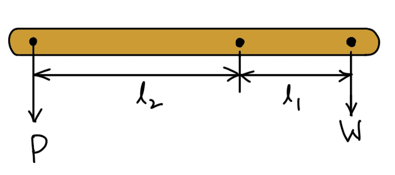
- The points A and B through which the load and effort are applied are known as load and effort points respectively.
- F is the fulcrum about which the lever is capable of turning.
- The perpendicular distance between the load point and fulcrum (l1) is known as the load arm.
- The perpendicular distance between the effort point and fulcrum (l2) is called the effort arm.
According to the principle of moments,
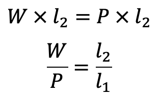
Mechanical Advantage
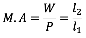
The ratio of the effort arm to the load arm i.e. l2 / l1 is called leverage.
A little consideration will show that if a large load is to be lifted by a small effort, then the effort arm should be much greater than the load arm. In some cases, it may not be possible to provide a lever with a large effort arm due to space limitations.
Therefore in order to obtain great leverage, compound levers may be used. The compound levers may be made of straight pieces, which may be attached to one another with pin joints. The bell-cranked levers may be used instead of a number of jointed levers. In a compound lever, the leverage is the product of leverages of various levers.
Hand Lever | Handbrake
The most common hand lever that we regularly see is the Handbrake in an automobile. we are going to design a hand lever commonly used by hand. For hand levers, about 400 N is considered the full force that a man is capable of exerting. About 100N is the mean force that a man can exert on the working handle of a machine, off and on for a full working day.
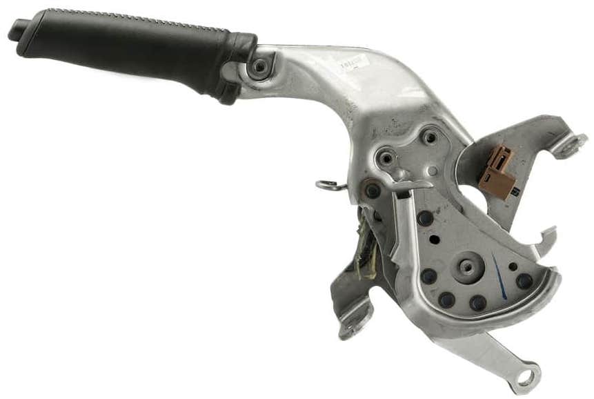
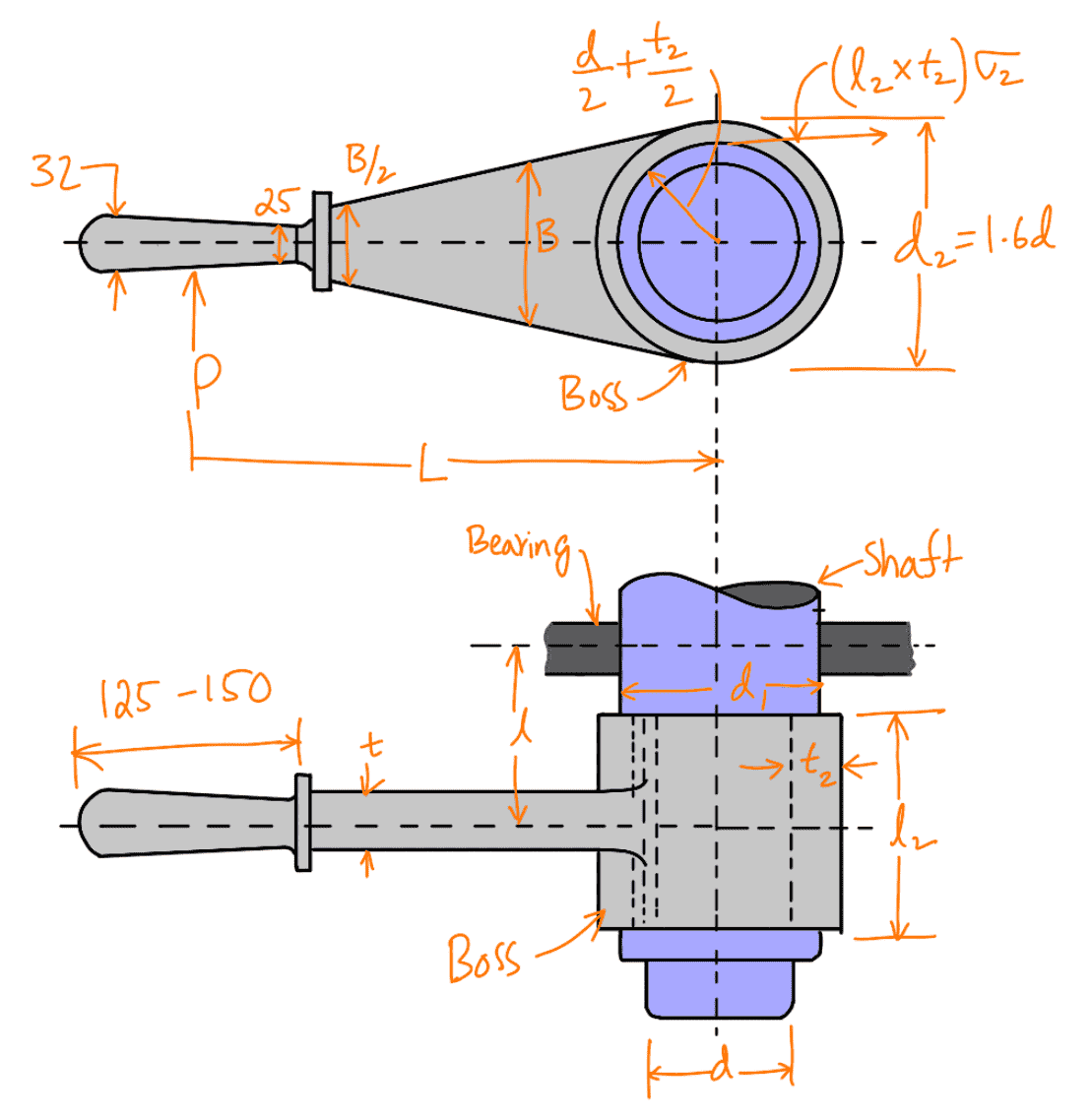
A hand lever with suitable dimensions and proportions is shown in the following figure.
Let
P = Force applied at the handle,
L = Effective length of the lever,
σt = Permissible tensile stress,
τ = Permissible shear stress.
For wrought iron, σt may be taken as 70 MPa and τ as 60 MPa. In designing hand levers, the following procedure may be followed :
- The diameter of the shaft ( d ) is obtained by considering the shaft under pure torsion. We know that twisting moment on the shaft,
T = P × L
and resisting torque
T = π/16 ×τ ×d3
From this relation, the diameter of the shaft (d) may be obtained
- The diameter of the boss (d2) is taken as 1.6 d and the thickness of the boss (t2) is 0.3d.
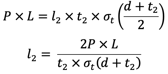
- The length of the boss (l2) may be taken from d to 1.25 d. It may be checked for a trial thickness t2 by taking moments about the axis. Equating the twisting moment (P × L) to the moment of resistance to tearing parallel to the axis, we get
- The diameter of the shaft at the centre of the bearing (d1) is obtained by considering the shaft in combined bending and twisting.
We know that the bending moment on the shaft,
M = P × l
and twisting moment,
T = P × L
∴ Equivalent twisting moment

We also know that the equivalent twisting moment,
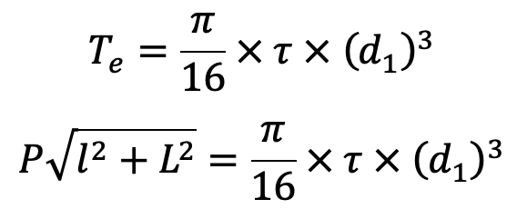
The length l may be taken as 2l2.
From the above expression, the value of d1 may be determined.
- The key for the shaft is designed as usual for transmitting a torque of P × L.
- The cross-section of the lever near the boss may be determined by considering the lever in
bending. It is assumed that the lever extends to the centre of the shaft which results in a stronger
section of the lever.
Let
t = Thickness of lever near the boss,
B = Width or height of lever near the boss.
We know that the bending moment on the lever,
M = P × L
Section modulus Z =1/6 × t ×B2
We know that the bending stress,

The width of the lever near the boss may be taken from 4 to 5 times the thickness of the lever, i.e. B = 4t to 5t. The width of the lever is tapered but the thickness (t) is kept constant. The width of the lever near the handle is B/2.
Additionally, we have already discussed different mechanical lever designs in the following articles. Check it out.
- Foot Lever (Brakes pedal, Foot pump Lever)
- Cranked Lever (Hoisting Winches)
- Lever Safety Valve
- Bell Crank Lever
- Rocker Arm for Exhaust Valve
Exercise Problem on Hand Lever | Handbrake
Can you solve an example Problem with Hand Lever Design?
Problem Statement: A Handbrake is 1m from the centre of the shaft to the point of application of 400 N load. The allowable tensile stress may be taken as 73MPa and the allowable shear stress as 70MPa. Please design a Handbrake.
Let us know if you can get the answers for the Diameter of the shaft (d), and the Dimensions of the key.

Leave a Reply