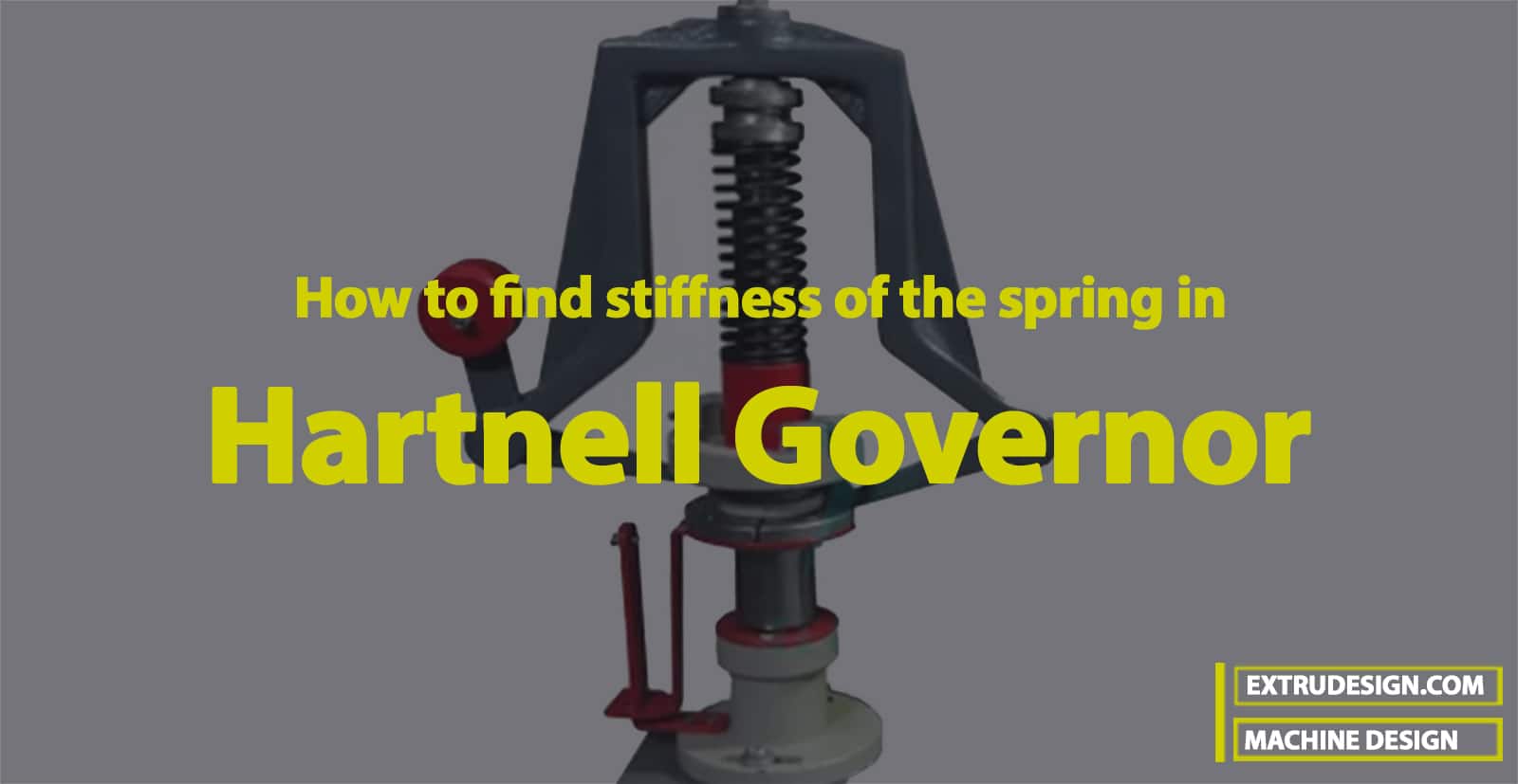
Hartnell Governor is basically a Centrifugal governor with a spring-loaded weight instead of dead weight on the sleeve to increase the speed of the balls required to lift the sleeve on the spindle. The Bell crank Lever holds two dead-weight balls for a Hartnell governor in order to regulate the fuel flow for the engines by maintaining the constant speed. Let us discuss how we can find the stiffness of the spring in Hartnell Governor. Also, design the Bell Crank Lever as well.
In the previous articles, we have different Mechanical Levers.
- Hand Lever (Hand Brake)
- Foot Lever (Brakes pedal, Foot pump Lever)
- Cranked Lever (Hoisting Winches)
- Lever Safety Valve
- Bell Crank Lever
- Rocker Arm for Exhaust Valve
In this article, we will discuss how we can determine the stiffness of the spring, the design of the bell crank lever, and the design of the balls for Hartnell Governor.
Bell Crank Lever
In a bell crank lever, the two arms of the lever are at right angles. Such types of levers are used in railway signaling, governors of Hartnell type, the drive for the air pump of condensers, etc. The bell crank lever is designed in a similar way as discussed in previous articles. The arms of the bell crank lever may be assumed of rectangular, elliptical, or I-section.
Stiffness of the Spring in Hartnell Governor
Let us discuss the complete design procedure for the bell crank lever with the following example.
In a Hartnell governor, the length of the ball arm is 190 mm, that of the sleeve arm is 140 mm, and the mass of each ball is 2.7 kg. The distance of the pivot of each bell crank lever from the axis of rotation is 170 mm and the speed when the ball arm is vertical is 300 rpm. The speed is to increase by 0.6 percent for a lift of 12 mm of the sleeve. We will find the necessary stiffness of the spring Design for the Hartnell Governor. Also, we will design the bell crank lever for the Hartnell Governor.
The permissible tensile stress for the material of the lever may be taken as 80 MPa and the allowable bearing pressure at the pins is 8 N/mm2.
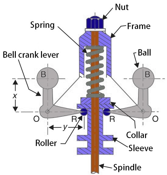
In order to find the stiffness of the spring, we will also design the bell crank lever and the dead weight of the balls.
Given design parameters of the Hartnell Governor are
Length of the ball arm x = 190mm
Length of the sleeve arm y = 140mm
Mass of each ball m = 2.7kg
Distance of the pivot of each bell crank lever from the axis of rotation r2 = 170mm =0.17m
Speed N2 =300r.p.m.
Lift of sleeve h = 12mm
Permissible tensile stress σt = 80 MPa = 80 N/mm2
Allowable bearing pressure at pins pb = 8 N/mm2
Stiffness of the Spring
Let
s1 = Stiffness of the spring.
We know that the minimum angular speed of the ball arm (i.e. when the ball arm is vertical)

Since the increase in speed is 0.6 percent, therefore the maximum angular speed of the ball arm,

We know that the radius of rotation at the maximum speed,
r1 = r2 + h × x ÷ y = 170 + 12 × 190 = 186.3mm = 0.1863m
The minimum and maximum position of the ball arm and sleeve arm is shown in the following figures (left) and (right) respectively.
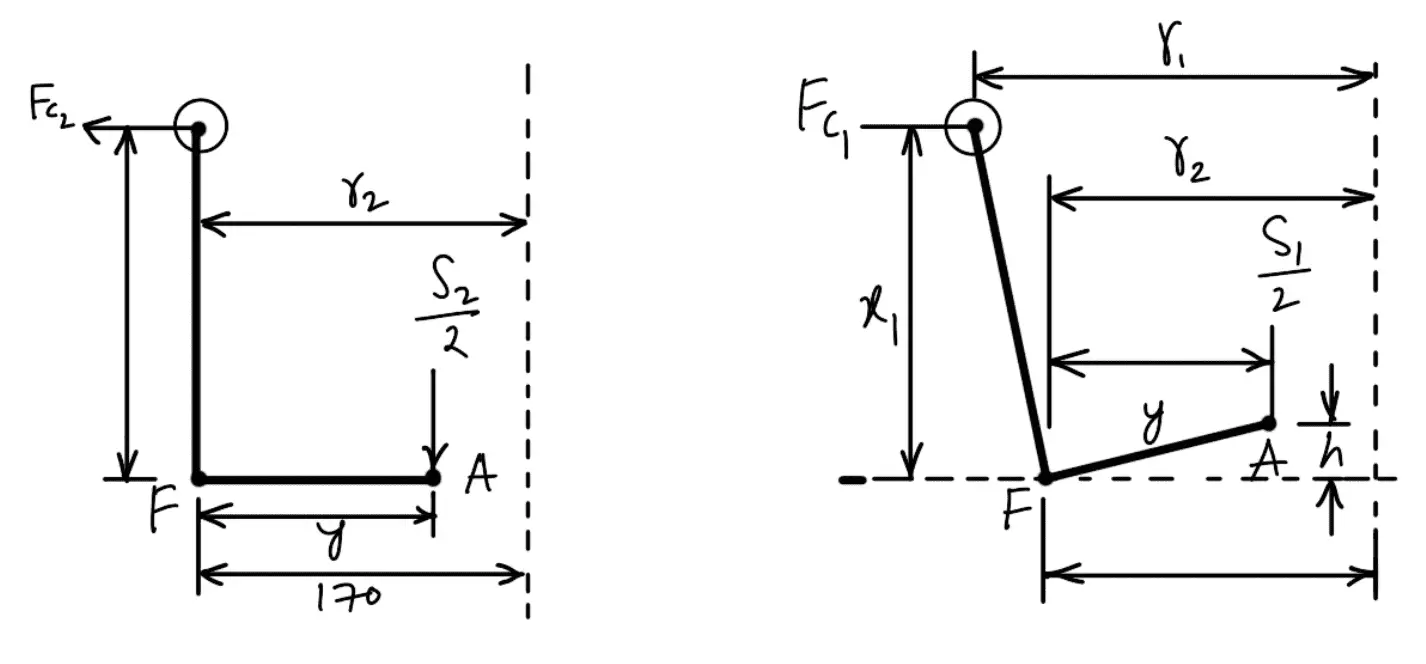
FC1 = Centrifugal force at the maximum speed = m (ω1)2 r1
FC2 = Centrifugal force at the minimum speed = m (ω2)2 r2
S1 = Spring force at the maximum speed (ω1)
S2 = Spring force at the minimum speed (ω2)
Taking moments about the fulcrum F of the bell crank lever, neglecting the obliquity effect of the arms (i.e. taking x1 = x and y1 = y) and the moment due to the mass of the balls, we have for the maximum position,
S1 = 2FC1 × x ÷ y
S1 = 2m(ω1)2 × r1 × x ÷ y
S1 = 2 × 2.7 × (31.6)2 × 0.1863 × 190 ÷ 140
S1 = 1364N
Similarly
S2 = 2FC2 × x ÷ y
S2 = 2m(ω2)2 × r2 × x ÷ y
S2 = 2 × 2.7 × (31.42)2 × 0.17 × 190 ÷ 140
S2 = 1230N
We already know that
S1 – S2 = h × s1
s1 = (S1 – S2) ÷ h
s1 = (1364 – 1230) ÷ 12
s1 = 11.16 N/mm
The Stiffness of the spring used for the Hartnell Governor is 11.16 N/mm.
Design of Bell Crank Lever
The bell crank lever is shown in the following figure. First of all, let us find the centrifugal force (or the effort P) required at the ball end to resist the load at A.
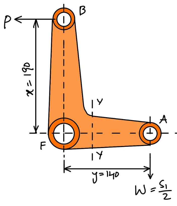
We know that the maximum load on the roller arm at A,
W = S1 /2 = 1364/2 = 682N
Taking moments about F, we have
P × x = W × y

We know that reaction at the fulcrum F,

(a) Design For Fulcrum Pin
Let
d = Diameter of the fulcrum pin,
l = Length of the fulcrum pin = 1.25 d
The fulcrum pin is supported in the eye which is integral with the frame for the spring. Considering the fulcrum pin in the bearing. We know that load on the fulcrum pin (RF),
847 = d × l × pb
847 = d × 1.25 d × 8
847 = 10 d2
d2 = 847/10
d2 = 84.7
d = 9.2
The diameter of the fulcrum pin is 10mm.
The length of the fulcrum pin t = 1.25 d = 1.25 × 10 = 12.5mm
Let us now check for the induced shear stress in the pin. Since the pin is in double shear, therefore load on the fulcrum pin (RF),
847 = 2 × π × d2 × τ
847 = 2 × π (10)2 τ
847 = 157.1 τ
τ = 847 / 157.1
τ = 5.4 N/mm2
τ = 5.4 MPa
This induced shear stress is very much within safe limits.
A brass bush 3 mm thick may be pressed into the boss. Therefore diameter of the hole in the lever or the inner diameter of the boss = 10 + 2 × 3 = 16mm
and outer diameter of the boss = 2d = 2 × 10 = 20mm
b) Design for Lever
The cross-section of the lever is obtained by considering the lever in bending. It is assumed that the lever arm extends up to the center of the fulcrum from the point of application of load. This assumption results in a slightly stronger lever. Considering the weakest section of failure at Y-Y (40 mm from the center of the fulcrum).
∴ Maximum bending moment at Y-Y = 682 (140–40) = 68200N-mm
Let
t = Thickness of the lever,
B = Depth or width of the lever.

We know that bending stress (σb),
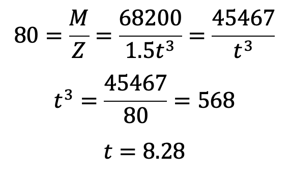
The thickness of the lever t is 10mm.
The depth or width of the lever is B = 3t = 3 × 10 = 30mm
Design for ball
Let r = Radius of the ball.
The balls are made of cast iron, whose density is 7200 kg/m3. We know that the mass of the ball (m),
2.7 = Volume × density
2.7 = 4 πr3 × 7200
2.7 = 30163 r3
r3 = 2.7 / 30163
r3 = 0.089/103
r = 0.0447m
r = 44.7
The Radius of the ball r is 45mm.
The ball is screwed to the end of the lever. The screwed length of the lever will be equal to the radius of the ball.
The maximum bending moment on the screwed end of the lever,
M = P × r = 502 × 45 = 22590N-mm
dc = Core diameter of the screwed length of the lever.

We know that bending stress (σb),
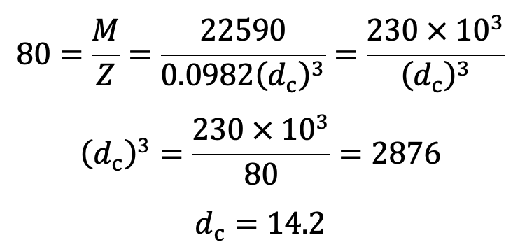
We shall take the nominal diameter of the screwed length of the lever as 16 mm.
Design for roller end A
Let
d1 = Diameter of the pin at A,
l1 = Length of the pin at A = 1.25 d1
We know that the maximum load on the roller at A,
W = S1 / 2 = 1364/2 = 682N
Considering the pin in the bearing. We know that load on the pin at A (W),
682 = d1 × l1 × pb
682 = d1 × 1.25d1 × 8
682 = 10(d1)2
(d1)2 = 682/10
(d1)2 = 68.2
d1 = 8.26
The Diameter of the pin at A is 10mm
The Length of the pin at A is l1 = 1.25 d1 = 1.25 × 10 = 12.5mm
Let us now check the pin for induced shear stress. Since the pin is in double shear, therefore load on the pin at A (W),

This induced stress is very much within safe limits.
The roller pin is fixed in the forked end of the bell crank lever and the roller moves freely on the pin.
Let us now check the pin for induced bending stress. We know that the maximum bending moment,

and section modulus of the pin,

Bending stress induced

This induced bending stress is within safe limits.
We know that the thickness of each eye of the fork,

and outer diameter of the eye, D = 2 d1 = 2 × 10 = 20mm
The outer diameter of the roller is taken slightly larger (at least 3 mm more) than the outer diameter of the eye. In the present case, the 23 mm outer diameter of the roller will be sufficient. The roller is not provided with a bush because, after sufficient service, the roller has to be replaced due to wear on the profile. A clearance of 1.5 mm is provided between the roller and fork on either side of the roller.
The total length of the pin,
l2 = l1 +2t1 + 2 × 1.5 = 12.5 + 2 × 6.25 + 3 = 28mm
This is how you can determine the stiffness of the spring, the design of the bell crank lever, and the design of the balls for Hartnell Governor.

Leave a Reply