ABSTRACT
IC Engines are tested to obtain information about the engine which cannot be determined by calculations, to confirm data used in the design, the validity of which is in doubt. The majority of the tests on internal combustion engines are carried out for commercial purposes in order to calculate and estimate their performance characteristics such as Brake Horse Power with guaranteed fuel consumption, quantity of lubricating oil required, quantity of cooling water required, steadiness of the engine loaded at different loads, overload carrying capacity of the engine which in turn are useful in the predicting betterment of economies.
The Computerized Test Rig Equipment is used to determine the Internal Pressure, Crank Angle, Combustion Rates, and Internal Temperatures instantaneously and very precisely up to 8 decimal digits which is almost not possible in conventional test rigs. The internal parameters of an engine are controlled effectively. The test rig is designed and constructed for a Petrol Engine, but can also be designed to perform effectively with fuels like Diesel and alternative fuels such as Ethanol, Methanol, Propane, Hydrogen, Bio-Diesel, P – Series fuels and Hybrid Fuels.
1. INTRODUCTION
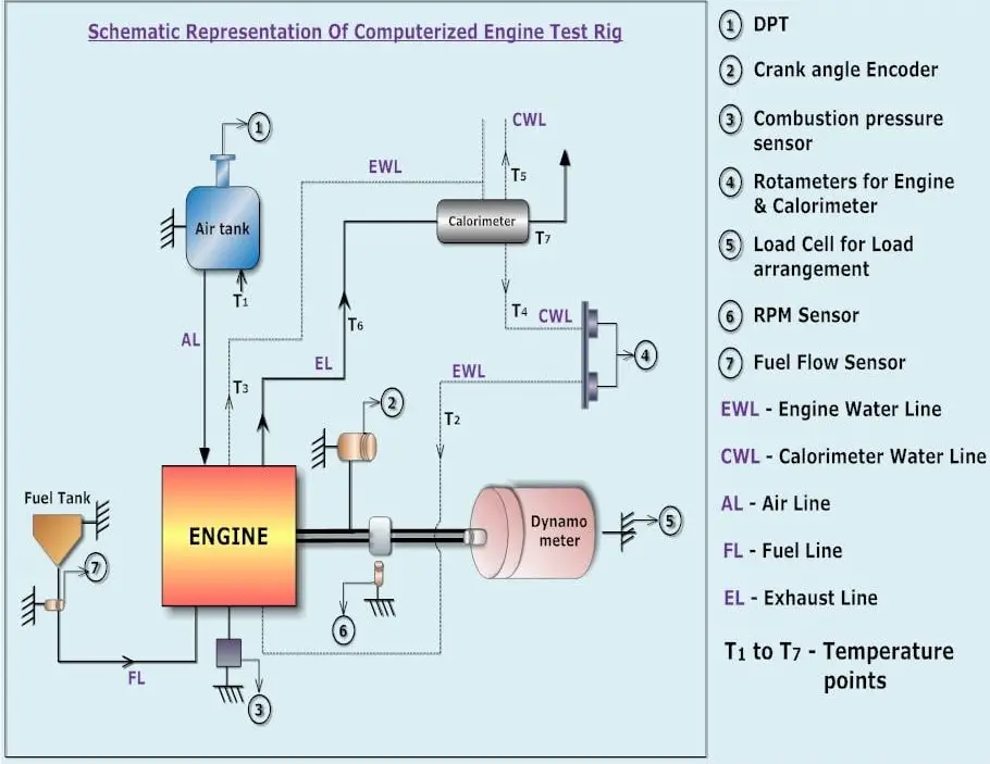
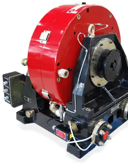
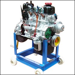
The Four Cylinder Four Stroke Water Cooled MPFI – PETROL Engine with Computerized Data Acquisition System is mounted on an aesthetically designed self – sustained frame. The engine and Eddy Current dynamometer are mounted on a centrally balanced-based frame. The base frame is fabricated with mild steel “C” sections. The engine and the dynamometer are coupled using standard Universal coupling. A standard air tank with orifice plates is fixed within the rig for measuring the actual volume of air drawn into the cylinder. The Differential transducer provided at the orifice plate facilities the measurement of airflow rate at the computer. Fuel sensor (weight loss) is mounted to the fuel tank measures the fuel consumed by the engine. This parameter is routed to the computer using necessary signal conditioning.
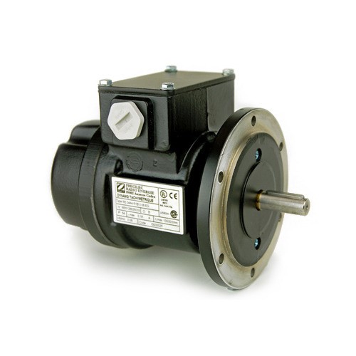
The thermocouples necessary for the measurements of temperature at various points in the system are suitably provided and routed to the computer via data scanner. Two Rotameters are provided to measure the water flow rate to calorimeter and engine jacket and this has to be entered manually to the computer. A pressure transducer is fitted to the cylinder head and is routed to the computer after special signal conditioning. The speed of the engine is measured using a Tacho – generator or non – contact proximity sensor, while the torque is measured using strain gauge based load cell. isolating to speed and torque are routed to the computer.
The main objective of the Computerized Test Rig is to
- Calculate Actual Volume of Air
- Determine Volumetric Efficiency
- Determine Specific Fuel Consumption
- Determine Brake Thermal Efficiency
- Determine Brake Power
- Determine Mechanical Efficiency
- Determine Frictional Power
- Draw the graph of Brake Power Vs Speed and Load
- Draw Heat Balance Sheet
- P – V and P – θ Diagrams
The panel is fabricated using WATERPROOF Plywood as per IS standard. This desk type panel houses all the instrumentation required for signal conditioning and data signal converting. Personal computer required for data acquisition is ergonomically housed within this panel. Power and control wiring is suitably marked using ferrule for easy troubleshooting. A standard circuit drawing is normally pasted behind the panel door.
The Schematic representation of Test Rig Equipment is as follows.
2. LITERATURE REVIEW
James H Tuttle et.al in 1980, upon working on a delay operation using Splined Camshaft, cams used to delay 0˚C, 60˚C, 80˚C, 96˚C proposed that, at 96˚C showed 6.5% lower specific fuel consumption at high load, about 24% lower nitric oxide emissions at mid – load and similar HC Emissions[1].
Saunders et.al in 1989, upon working on Late Intake Valve Closings (LIVC), achieved Variable LIVC by means of a secondary camshaft driven by a variable geometry timing belt, proposed that LIVC shows 6 – 13% showed improvement in BSFC at half load. The same for LIVC with Variable Compression Ratio was about 12 – 20% [2].
Jerald A. Caton (2000) analysed the complete version of the thermodynamic engine cycle simulation for spark – ignition engine. The instructional version of cycle simulation used constant specific heats as compared to using variable properties and composition for the complete simulation. Mass fraction burned was calculated using Wiebe function. Woschni heat transfer coefficient model was used to calculate heat transfer to the cylinder gases. For the proper selection of constant properties, the global engine performance parameters and was obtained the instructional version of the simulation were in close 17 agreement to the values obtained from using the complete version of the simulation [3].
Kodah et.al (2000) describes a simple analysis for the prediction of pressure within a spark ignition engine. This is done by modelling the combustion process using the Wiebe function approach, which is an exponential function in the form to calculate the rate of fuel burned. By careful selection of A and M, any spark ignition engine with any combustion chamber shape and any specified dimensions can be assessed by this model. The validity of this model has been tested by comparing the model results with those obtained from running the engine under the same operating conditions. The results obtained from the theoretical model were compared with those from the experimental data which show a good agreement. Effects of the many operating conditions, such as compression ratio, engine speed, and spark timing have also been studied in this work [4].
Lawrence Mianzo and Huei Peng (2000) developed the cylinder-by-cylinder model of a variable valve timing 4-cylinder engine. The model includes the cylinder and manifold mass, temperature, burned gas residual, and pressure dynamics, including combustion effects, as well as the valve actuator dynamics. The cylinder – by – cylinder model is used to obtain a cycle-averaged mapping between torque at given engine speed and intake valve timing, which is suitable for future control design implementations [5].
2.1 BRIEF HISTORY OF ENGINES
· 1206: Al-Jazari described a double-acting reciprocating piston pump with a crankshaft-connecting rod mechanism.
· 1509: Leonardo da Vinci described a compressionless engine.
· 1862: German inventor Nikolaus Otto designed an indirect – acting free -piston compressionless engine whose greater efficiency won the support of Langen then most of the market, which at that time was mostly for small stationary engines fuelled by lighting gas.
· 1876 Nikolaus Otto, working with Gottlieb Daimler and Wilhelm Maybach, developed a practical four-stroke cycle (Otto cycle) engine. The German courts, however, did not hold his patent to cover all in-cylinder compression engines or even the four-stroke cycle, and after this decision, in-cylinder compression became universal.
· 1879 Karl Benz, working independently, was granted a patent for his internal combustion engine, a reliable two-stroke gas engine, based on Nikolaus Otto’s design of the four-stroke engine. Later, Benz designed and built his own four-stroke engine that was used in his automobiles, which became the first automobiles in production.
· 1882 James Atkinson invented the Atkinson cycle engine. Atkinson’s engine and one power phase per revolution together with different intake and expansion volumes, making it more efficient than the Otto cycle.
· 1892 Rudolf Diesel developed his Carnot heat engine type motor burning powdered coal dust.
· 1896 Karl Benz invented the boxer engine, also known as the horizontally opposed engine, in which the corresponding pistons reach the top dead centre at the same time, thus balancing each other in momentum
· 1900 Rudolf Diesel demonstrated the diesel engine in the 1900 Exposition Universelle (World’s Fair) using peanut oil (see biodiesel).
· 1900 Wilhelm Maybach designed an engine built at Daimler Motoren Gesellschaft following the specifications of Emil Jel linek —who required the engine to be named Daimler – Mercedes after his daughter. In 1902 automobiles with that engine were put into production by DMG.
A heat engine is a machine, which converts heat energy into mechanical energy. The
combustion of fuels such as coal, petrol, and diesel generates heat. This heat is supplied to a working substance at high temperature. By the expansion of this substance in suitable machines, heat energy is converted into useful work. Heat engines can be further divided into two types:
In a steam engine, the combustion of fuel takes place outside the engine and the steam
thus formed is used to run the engine. Thus, it is known as the External Combustion Engine.
In the case of the Internal Combustion Engine, the combustion of fuel takes place inside the engine cylinder itself.
The IC engines may be classified as follows
- According to Cycle of Operation
- According to Cycle of Combustion
- Otto Cycle Engine ( Combustion at Constant Volume)
- Diesel Cycle Engine (Combustion at Constant Pressure)
- Dual – Combustion or Semi-Diesel Cycle Engine (Combustion partly at constant volume and partly at constant pressure)
- According to the Arrangement of Cylinder
- Horizontal Engine
- Vertical Engine
- V – type Engine
- Radial Engine
- According to their uses
- Stationary Engine
- Portable Engine
- Marine Engine
- Automobile Engine
- Aero Engine
- According to the fuel employed and the method of fuel supply to the engine cylinder
- Oil Engine
- Petrol Engine
- Gas Engine
- Kerosene Engine
- Carburettor, hot bulb, solid injection and air injection engine.
- According to the speed of the Engine
- Low-Speed Engine
- Medium Speed Engine
- High-Speed Engine
- According to the method of ignition
- According to the method of cooling the cylinder
- Air – Cooled Engine
- Water – Cooled Engine
- According to the method of Governing
- Hit and miss governed Engine
- Quality governed Engine
- Quantity Governed Engine
- According to Valve Arrangement
- Overhead Valve Engine
- L – Head type Engine
- T – Head type Engine
- F – Head type Engine
- According to the number of cylinders
- Single Cylinder Engine
- Multi-Cylinder Engine
A petrol engine is an internal combustion engine with spark-ignition, designed to run on petrol and similar volatile fuels.
In most petrol engines, the fuel and air are usually mixed after compression. The pre-mixing was formerly done in a carburettor, but now it is done by electronically controlled fuel injection, except in small engines where the cost/complication of electronics does not justify the added engine efficiency.
The process differs from a diesel engine in the method of mixing the fuel and air, and in using spark plugs to initiate the combustion process. In a diesel engine, only air is compressed and the fuel is injected into very hot air at the end of the compression stroke, and self-ignites.
The four-stroke petrol engines are the most commonly used engines in today’s automobile sector and vehicles, both in cases of a single cylinder and multi-cylinder applications. Four stroke petrol engine commonly used in cars, motorbikes, scooters, small propeller aircraft, formula one, small motor powered boats, auto-rickshaw, water spray systems, etc. The petrol four-stroke engines have wide applications since the higher value of the low-end punch capabilities of the engines.
2.2 PRINCIPLES OF OPERATION
2.2.1 FOUR-STROKE CYCLE DIESEL ENGINE
In four-stroke cycle engines, there are four strokes completing two revolutions of the crankshaft. These are respectively, the suction, compression, power and exhaust strokes. In Fig, the piston is shown descending on its suction stroke. Only pure air is drawn into the cylinder during this stroke through the inlet valve, whereas, the exhaust valve is closed.
These valves can be operated by the cam, push rod and rocker arm. The next stroke is the compression stroke in which the piston moves up with both the valves remaining closed. The air, which has been drawn into the cylinder during the suction stroke, is progressively compressed as the piston ascends. The compression ratio usually varies from 14:1 to 22:1.
The pressure at the end of the compression stroke ranges from 30 to 45 kg/cm2. As the air is progressively compressed in the cylinder, its temperature increases, until when near the end of the compression stroke, it becomes sufficiently high (650-80O˚C) to instantly ignite any fuel that is injected into the cylinder. When the piston is near the top of its compression stroke, a liquid hydrocarbon fuel, such as diesel oil, is sprayed into the combustion chamber under high pressure (140-160 kg/cm2), higher than that existing in the cylinder itself. This fuel then ignites, being burnt with the oxygen of the highly compressed air. During the fuel injection period, the piston reaches the end of its compression stroke and commences to return on its third consecutive stroke, viz., power stroke. During this stroke the hot products of combustion consisting chiefly of carbon dioxide, together with the nitrogen left from the compressed air expand, thus forcing the piston downward. This is only the working stroke of the cylinder.
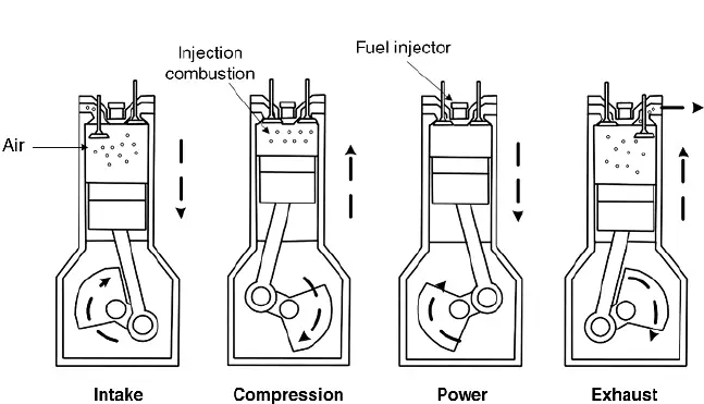
During the power stroke the pressure falls from its maximum combustion value (47-55 kg/cm2), which is usually higher than the greater value of the compression pressure (45kg/cm2), to about 3.5-5 kg/cm2 near the end of the stroke. The exhaust valve then opens, usually a little earlier than when the piston reaches its lowest point of travel. The exhaust gases are swept out on the following upward stroke of the piston. The exhaust valve remains open throughout the whole stroke and closes at the top of the stroke.
The reciprocating motion of the piston is converted into the rotary motion of the crankshaft by means of a connecting rod and crankshaft. The crankshaft rotates in the main bearings, which are set in the crankcase. The flywheel is fitted on the crankshaft in order to smoothen out the uneven torque that is generated in the reciprocating engine.
2.2.2 FOUR-STROKE SPARK IGNITION ENGINE
In this, gasoline is mixed with air, broken up into a mist and partially vaporized in a Carburettor. The mixture is then sucked into the cylinder. There it is compressed by
the upward movement of the piston and is ignited by an electric spark. When the mixture is burned, the resulting heat causes the gases to expand. The expanding gases exert a pressure on the piston (power stroke). The exhaust gases escape in the next upward movement of the piston. The strokes are similar to those discussed under four-stroke diesel engines. The compression ratio varies from 4:1 to 8:1 and the air-fuel mixture from 10:1 to 20:1.
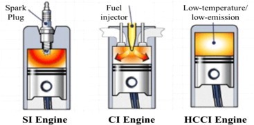
2.3 COMPARISON OF CI AND SI ENGINES
The CI engine has the following advantages over the SI engine.
- Reliability of the CI engine is much higher than that of the SI engine. This is because in case of the failure of the battery, ignition or Carburettor system, the SI engine cannot operate, whereas the CI engine, with a separate fuel injector for each cylinder, has less risk of failure.
- The distribution of fuel to each cylinder is uniform as each of them has a separate injector, whereas in the SI engine the distribution of fuel mixture is not uniform, owing to the design of the single Carburettor and the intake manifold.
- Since the servicing period of the fuel injection system of the CI engine is longer, its maintenance cost is less than that of the SI engine.
- The expansion ratio of the CI engine is higher than that of the SI engine; therefore, the heat loss to the cylinder walls is less in the CI engine than that of the SI engine. Consequently, the cooling system of the CI engine can be of smaller dimensions.
- The torque characteristics of the CI engine are more uniform which results in better top gear performance.
- The CI engine can be switched over from part load to full load soon after starting from cold, whereas the SI engine requires warming up.
- The fuel (diesel) for the CI engine is cheaper than the fuel (petrol) for SI engine.
- The fire risk in the CI engine is minimized due to the absence of the ignition system.
- On part load, the specific fuel consumption of the CI engine is low.
2.4 COMPARISON OF FOUR–STROKE AND TWO-STROKE CYCLE ENGINES
| ASPECTS | FOUR -STROKE ENGINES | TWO-STROKE ENGINES |
| Completion of Cycle | The Cycle is Completed in Four Strokes of the piston or in two revolutions of the crankshaft. | The Cycle is completed in Two-strokes of the piston or in one revolution of the crankshaft |
| Flywheel | Heavier Flywheel is needed because of non-uniform turning movement | Lighter Flywheel is needed because of uniform turning movement |
| Power produced for the same size of Engine | Because of one power stroke for two revolutions, power produced is low | Because of one power stroke for one revolution, power produced is more |
| Cooling and Lubrication Requirements | Lesser Cooling and Lubrication requirements. Lesser rate if wear and tear | Greater Cooling and Lubrication requirements. Great wear and tear. |
| Valve and Valve Mechanism | Contains Valve and Valve Mechanism | No valve mechanism, only ports |
| Initial Cost | Because of heavy weight and complication of valve mechanism, higher is initial cost | Because of light weight and simplicity, cheaper is initial cost |
| Volumetric Efficiency | More due to more time of induction | Less due to lesser time of induction |
| Thermal and Part – Load Efficiencies | Higher Thermal Efficiency, Better Part load efficiency | Lower Thermal Efficiency and lower part load efficiency |
| Applications | Used where efficiency is important; in cars, buses, trucks, tractors, industrial engines, aeroplane, power generators etc. | Used in very small sizes only, lawn movers, scooters motorcycles. Used in very large sizes more than 60 cm bore, for ship propulsion because of low weight and compactness. |
2.5 COMPARISON BETWEEN A PETROL ENGINE AND A DIESEL ENGINE
| PETROL ENGINE | DIESEL ENGINE |
| Air – Petrol mixture is sucked in the engine cylinder during suction stroke. | Only air is sucked during suction stroke. |
| Spark plug I used. | Employs an injector. |
| Power is produced by spark ignition. | Power is produced by compression ignition. |
| Thermal efficiency up to 25% | Thermal efficiency up to 40% |
| Occupies less space. | Occupies more space. |
| More running cost. | Less running cost. |
| Light in weight. | Heavy in weight. |
| Fuel (Petrol) costlier. | Fuel (Diesel) cheaper. |
| Petrol being volatile is dangerous. | Diesel is non – dangerous as it non – volatile. |
| Pre – Ignition possible. | Pre – Ignition not possible. |
| Works on Otto Cycle. | Works on Diesel Cycle. |
| Less dependable. | More dependable. |
| Used in cars and motor cycles. | Used in heavy duty vehicles like trucks, buses and heavy machinery. |
2.6 ADVANTAGES AND DISADVANTAGES OF TWO-STROKE CYCLE OVER FOUR-STROKE CYCLE ENGINES
ADVANTAGES
- The two-stroke cycle engine gives one working stroke for each revolution of the crankshaft. Hence theoretically the power developed for the same engine speed and cylinder volume is twice that of the four-stroke cycle engine, which gives only one working stroke for every two revolutions of the crankshaft. However, in practice, because of poor scavenging, only 50-60% extra power is developed.
- Due to one working stroke for each revolution of the crankshaft, the turning moment on the crankshaft is more uniform. Therefore, a two-stroke engine requires a lighter flywheel.
- The two-stroke engine is simpler in construction. The design of its ports is much simpler and their maintenance easier than that of the valve mechanism.
- The power required overcoming the frictional resistance of the suction and exhaust strokes are saved, resulting in some economy of fuel.
- Owing to the absence of the cam, camshaft, rockers, etc. of the valve mechanism, the mechanical efficiency is higher.
- The two-stroke engine gives fewer oscillations.
- For the same power, a two-stroke engine is more compact and requires less space than a four-stroke cycle engine. This makes it more suitable for use in small machines and motorcycles.
- A two-stroke engine is lighter in weight for the same power and speed especially when the crankcase compression is used.
- Due to its simpler design, it requires fewer spare parts.
- Two – stroke cycle engine can be easily reversed if it is of the valveless type.
DISADVANTAGES
- The Scavenging being not very efficient in a two-stroke engine, the dilution of charge takes place which results in poor thermal efficiency.
- The two-stroke spark ignition engines do not have a separate lubrication system and normally, lubricating oil is mixed with the fuel. This is not as effective as the lubrication of a four-stroke engine. Therefore, the parts of the two-stroke engine are subjected to greater wear and tear.
- In a spark ignition two-stroke engine, some of the fuel passes directly to the exhaust. Hence, the fuel consumption per horsepower is comparatively higher.
- With heavy loads, a two-stroke engine gets heated up due to the excessive heat produced. At the same time, the running of the engine is riot very smooth at light loads.
- It consumes more lubricating oil because of the greater amount of heat generated.
- Since the ports remain open during the upward stroke, the actual compression starts only after both the inlet and exhaust ports have been closed. Hence, the compression ratio of this engine is lower than that of a four-stroke engine of the same dimensions. As the efficiency of an engine is directly proportional to its compression ratio, the efficiency of a two-stroke cycle engine is lower than that of a four-stroke cycle engine of the same size.
3. MATERIALS AND METHODS
Petrol is used as the fuel in the performance analysis. Petrol is a Petroleum derived liquid, primarily used as a fuel in Spark Ignited Internal Combustion Engines. It mainly consists of organic compounds, obtained by fractional distillation of petroleum, enhanced with a variety of additives.
Petrol is used in Petrol Engines. Some of its properties are
- Energy Content: 34.2 MJ/L
- Torque for 10 L Engine: 300Nm at 4000 RPM
- Power: 600 HP at 5500 RPM
- The heat of Vaporization: 305 KJ/Kg
- Auto Ignition Temperature: 228 – 470˚C
- Research Octane Number: 95
- Engine Octane Number: 85
- Boiling Point: 27 – 225˚C
- Density: 740 Kg/m3
·SPECIFIC FUEL CONSUMPTION: The Ratio of fuel consumption per unit time ( Kg/hr ) to power produced by the Engine is Specific Fuel Consumption.
Units: Kg/ J
BRAKE POWER: The power developed by an engine at the output shaft is called the Brake Power.
Units: kW

N = speed in rpm
W = Load in Kg
C = 2000 = dynamometer constant
INDICATED POWER The total power developed by combustion of fuel in the combustion chamber is called Indicated Power
Units: kW
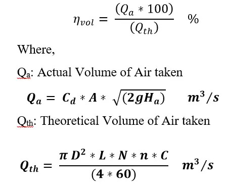
VOLUMETRIC EFFICIENCY Ratio of the mass density of the Air – Fuel mixture drawn into the cylinder at atmospheric pressure (during the intake stroke) to the mass density of the same volume of air in the intake manifold.
THERMAL EFFICIENCY: It is the ratio of indicated work done to the energy supplied by the fuel.

MECHANICAL EFFICIENCY: Mechanical efficiency is the parameter that gives the effectiveness of an engine in transforming its input energy to output energy.

CRANK ANGLE: The angle of rotation of a crankshaft measured from the position in which the piston is at its highest point known as Top dead centre (TDC).
MEAN EFFECTIVE PRESSURE: Mean Effective Pressure is defined as the pressure which is thought to be acting on the piston throughout the power stroke.
If it is based on IP, it is called Indicated Mean Effective Pressure and if it is based on BP, it is called Brake Mean Effective Pressure. Similarly, Frictional Mean Effective Pressure can be defined as
Fm.e.p. = Im.e.p. – Bm.e.p.
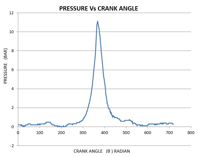
FUEL – AIR RATIO Fuel – Air Ratio is the ratio of the mass of fuel to the mass of air in the fuel-air mixture.
P – THETA DIAGRAM
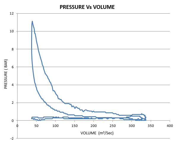
The device which measures the variations of the pressure in the cylinder over a part or full cycle is called an indicator and the plot of such information obtained is called an indicator diagram. Basically, there are two types of the indicator diagram
- Pressure-Volume (PV) Plot
- Pressure – Crank Angle (P – Theta) Plot
3.1 ENGINE SPECIFICATIONS
Make: MARUTI SWIFT –MPFI
- Four Cylinder.
- Water Cooled.
- 1197cc, 20 kW (approx).
- Cylinder Bore : 73.0mm
- Stroke Length: 71.5 mm
- Compression Ratio : 9.0:1
DYNAMOMETER
Make: TECHNOMECH
- Eddy Current Type.
- Water Cooled – Minimum 4kg/cm2 pressure required
- Load Measurement – Strain Gauge based Load Cell
- Max. Capacity: 30kW
- Max Speed: 3000 rpm
- Coupled using a STANDARD UNIVERSAL JOINT coupling.
AIR TANK
Make: MECHTRIX
- Cubical type.
- Mild Steel.
- Orifice Dia – 30 mm.
CALORIMETER
Make: MECHTRIX
- Inner & outer covering – MS/GI.
- Attachment – through the flange.
- Powder coated.
FUEL TANK
Make: STANDARD/FABRICATED
- Material: SS Finished.
- 15 Lts Capacity.
COMPUTER
Make: ASSEMBLED.
3.2 MEASUREMENTS
CYLINDRICAL HEAD PRESSURE
- Type – Piezoelectric.
- Water Cooled.
- Stand Alone Signal Conditioning.
- Range: 350bar Make – PCB.
ROTAMETER
- Type – ACRYLIC.
- Range – 0 to 15 Lpm for Engine Cooling.
- Range – 0 to 10 Lpm for Calorimeter Cooling
- Make – CONTROL DEVICES.
ENGINE SPEED
- Type – Tacho-Generator / Non-Contact Proximity.
- Range – 0 – 9999 RPM.
- Stand Alone Signal Conditioning.
- Make – STANDARD.
TEMPERATURE MEASUREMENT
- Type – “K – Type”.
- Range – 0 – 600° C.
- Stand Alone Signal Conditioning.
- Make – STANDARD
TORQUE AT DYNAMOMETER
- Type – Strain Gauge.
- Range – 0 – 50 Kgs.
- Stand Alone Signal Conditioning.
- Make – TECHNOMECH.
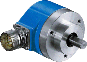
CRANK ANGLE DECODER
- Speed – 5500rpm with TDC pulse.
- Stand Alone Signal Conditioning.
- Make – ENCODER1S INDIA.
AIR FLOW
- Type – Differential Pressure Transducer.
- Range – 0 to 125mm of WC
- Stand Alone Signal Conditioning
- Make – STANDARD.
FUEL FLOW
- Type – Strain Gauge.
- Range – 0 – 15 Kg.
- Stand Alone Signal Conditioning
- Make – SURAKSHA SENSORS.
DATA ACQUISITION & SOFTWARE Development: MECHTRIX
- Resolution – 16 bit.
- Operating System – Windows 7 & later.
Software type – Run Time.
- The software program provides a complete platform for Trend Analysis.
HISTORIC REPORT GENERATION
Graph plotting facilities (IP, IMEP, and FP).The software is capable of processing the experimental values to obtain calculated values. The software is designed for individual equipment and can also be upgraded for a centralized application as per the customer requirement.
4. RESULT ANALYSIS
4.1 OBSERVATIONS
PERFORMANCE TEST
The following are the values observed while experimenting with the performance of the 4 Stroke 4 Cylinder Petrol Engine.
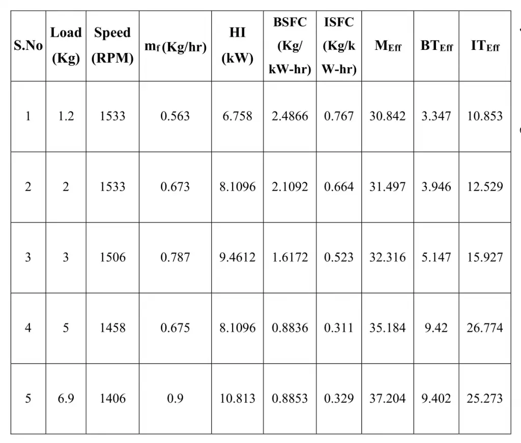
| HI: Heat Input | BSFC: Specific Fuel Consumption in terms of BP |
| ISFC: Specific Fuel Consumption in terms of IP | MEff : Mechanical Efficiency |
| BTEff : Brake Thermal Efficiency | ITEff : Indicated Thermal Efficiency |
VOLUMETRIC EFFICIENCY
The following are the values observed while experimenting with the volumetric efficiency of the 4 Stroke 4 Cylinder Petrol Engine.
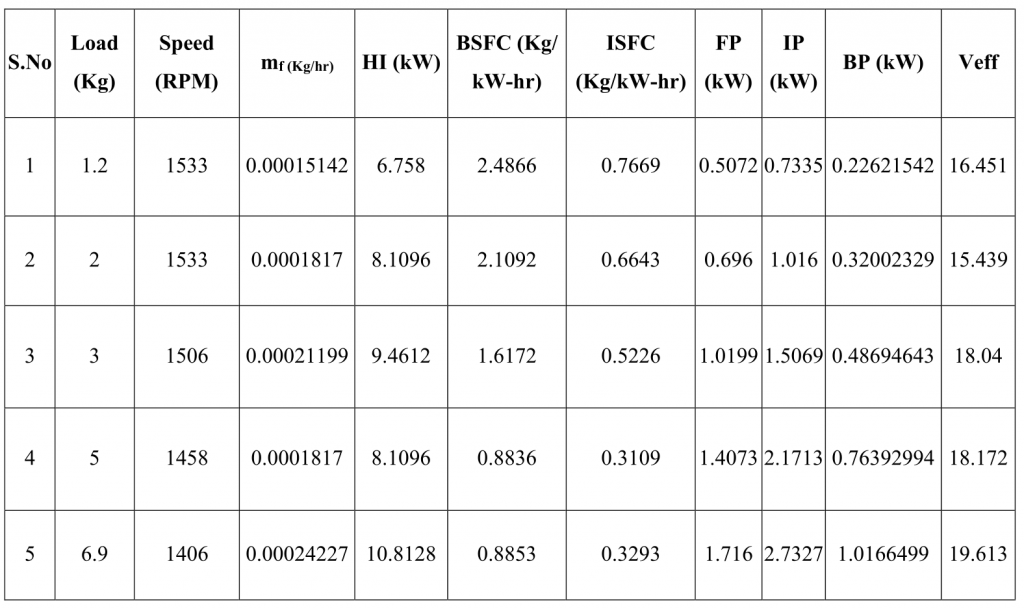
| FP: Frictional Power | BP: Brake Power |
| IP: Indicated Power | mf : Mass of Fuel Consumed |
HEAT BALANCE
The following are the results observed while working on the Heat Balancing of the Engine.
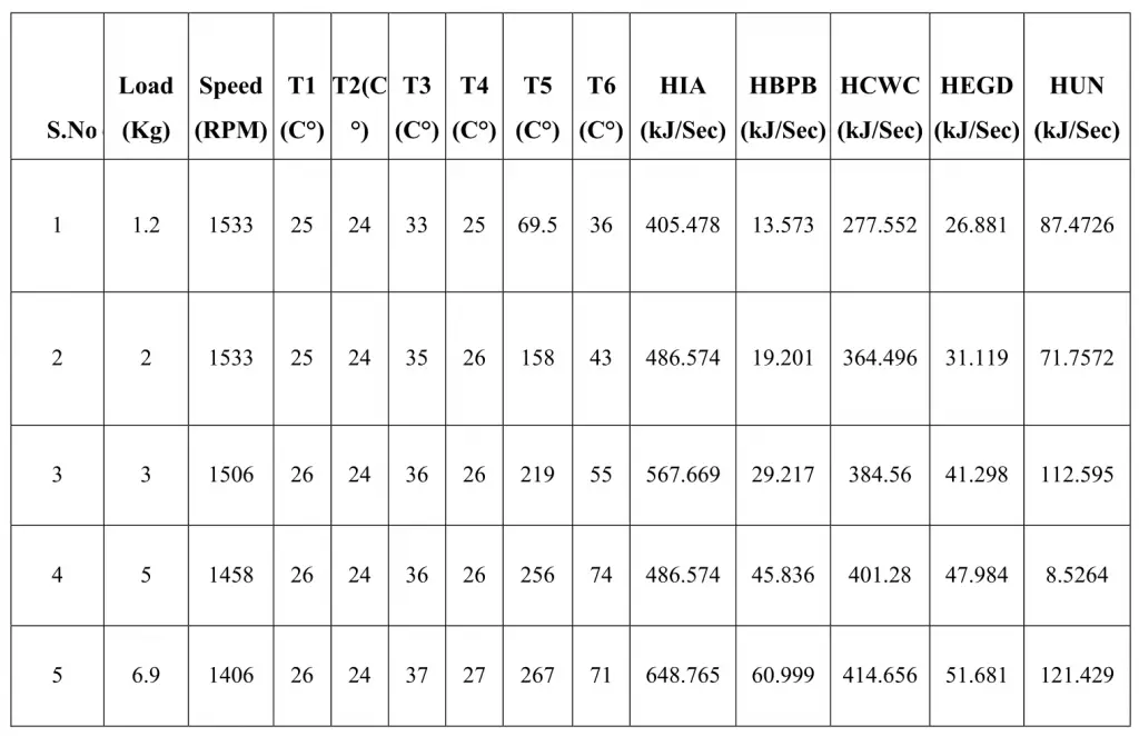
| HI: Actual Heat Inpu | HEG: Heat to Exhaust Gases |
| HBP: Hear to Brake Power | HUN: Heat Unaccounted |
| HCW: Heat to Cooling Water |
PRESSURE – THETA DIAGRAM
PRESSURE – VOLUME DIAGRAM
CONCLUSION AND FUTURE SCOPE
The Computerized Test Rig Equipment used for estimation and calculation of the performance of 4 Stroke 4 Cylinder Petrol Engine is very helpful in the determination of several parameters like Crank Angle, Cylinder Internal Combustion Pressure, Fuel Flow Rate etc., very effectively than the conventional test rig equipment. The results thus obtained are far accurate and graphs thus obtained are very precise. The Data Acquisition System has an important role in the retrieval of experimental results as it can extract values precisely up to 8 decimal points. The conventional test rig is not capable of producing precise results. Using computer-controlled electronic sensors like Pressure Transducer, Crank Angle Encoder, RPM Sensor and Fuel Flow Sensor the results are inclined to 6N Accuracy and the chance for errors in measurement is almost zero.
The computerized test rig can also be implied to alternative fuels for improving the eco-friendly emissions which are grabbing attention in the field of IC Engines nowadays. Further, the test rig can also be developed by simulating the working of the engine which can pave way for further research in increasing the efficiency of the engine both volumetrically and thermally.
The test rig is designed and constructed for a Petrol Engine, but can also be designed to perform effectively with fuels like Diesel and alternative fuels such as Ethanol, Methanol, Propane, Hydrogen, Bio-Diesel, P – Series fuels and Hybrid Fuels.
ACKNOWLEDGEMENT
This project would not have been possible without the help and guidance of various people.
We express our deepest gratitude to Dr. CH KESAVA REDDY, Sr. Assistant Professor, Department of Mechanical Engineering (Mechatronics) for his invaluable guidance at all walks of our work. His support has played a vital role in carrying out the project.
We are very thankful to Dr. P VENKATA RAMANA, Professor, Department of Mechanical Engineering (Mechatronics) for his help and guidance in turning the structure of the project.
We are also grateful to Prof. K SUDHAKAR REDDY, Head of the Department, Mechanical Engineering (Mechatronics) for readily accepting our request to carry out work in the Department Laboratories and enquiring the updates of the project whenever possible.
We would firstly like to thank Prof. G CHANDRA MOHAN REDDY, Principal, Mahatma Gandhi Institute of Technology for inspiring us and supporting us constantly during the project work.
We thank every Teaching and Non-Teaching Faculty who have stood with us in the successful completion of our project.
REFERENCES
- Review Paper on Four Stroke Petrol Engine | Sagar P Mistry et.al | (IJEDR) International Journal of Engineering Development and Research | Volume 4, Issue 4 | 2016
- Development of Four Stroke Cylinder HSDI Diesel Engine Test Bed | Sanaur Rehman et.al | International Journal of Innovative Research in Science (IJIRS) | Volume 2 Issue 10 | October 2013
- Experimental Performance Analysis of Single Cylinder Two Stroke Petrol Engine Using Gasoline and LPG | Maneesh Kumar Dubey et.al | International Journal of Mechanical Engineering and Robotics Research (
IJMERR ) | Volume 3, Issue 4 | October 2014 - Performance Evaluation of Four Stroke SI Engine with and without Oxyrich Air Energizer at 1000 RPM | Nilesh T Dhokane et.al | International Journal of Current Engineering and Technology (IJCET) | Issue 4 | March 2016
- Performance Analysis of Two Stroke Petrol Engine in the Basis of Variation in Carburetor Main – Jet Diameter | Abhishek Chakraborty et.al | International Journal of Engineering Research and Applications (IJERA) | Volume 3, Issue 4 | Jul – Aug 2013

Leave a Reply