Do you know what is Fatigue Failure? Fatigue failure refers to the failure of the machine component due to repeated or cyclic loading. Due to the fluctuation in the stress, this failure occurs. Let’s discuss the Fatigue failure briefly.

Fatigue Failure
Fatigue Failure is defined as the brittle fractures that occurred while a repeated load or cyclic load is applied to a machine component. This brittle fracture can be regardless of the material type whether it is a ductile or brittle material.
We can understand this scenario by considering a wire(Solid) of comparatively less diameter with the length as shown in the figure.
When you try to break it with the bare hands by bending it on both sides as shown in the below figure.
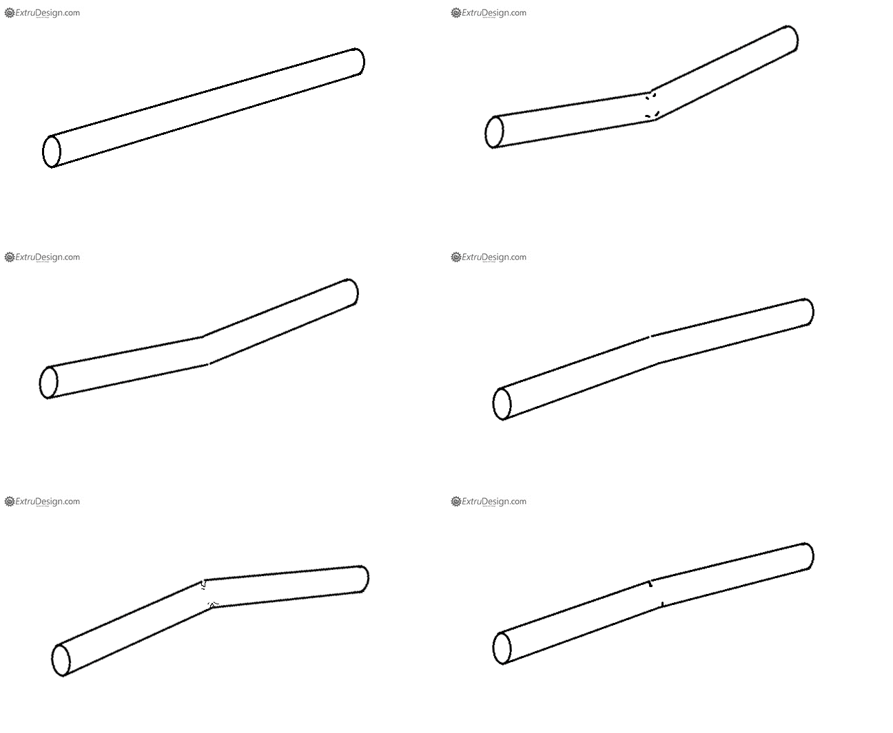
At some point, The solid wire will be definitely broken due to the brittle fractures induced in the solid wire due to the application of the repeated load. The weakening of a material caused by repeatedly applied loads can be said as a fatigue failure.
See the picture representing where the crack started (Origin) and the complete fatigue zone and the final failure zones.
These cyclic or repeated loads are known as fatigue loads.
We have seen in many types of service applications, metal parts subjected to repetitive or cyclic stresses eventually fail due to fatigue loading at a much lower stress than that which the part can withstand under the application of a single static stress. These failures that occur under repeated or cyclic stressing are called fatigue failures.
Examples of machine parts in which fatigue failures are common are moving parts such as shafts, connecting rods, and gears.
Some estimates of failures in machines attribute about 80 percent to the direct action of fatigue failures. A typical fatigue failure of sample specimens is shown below in Figure.
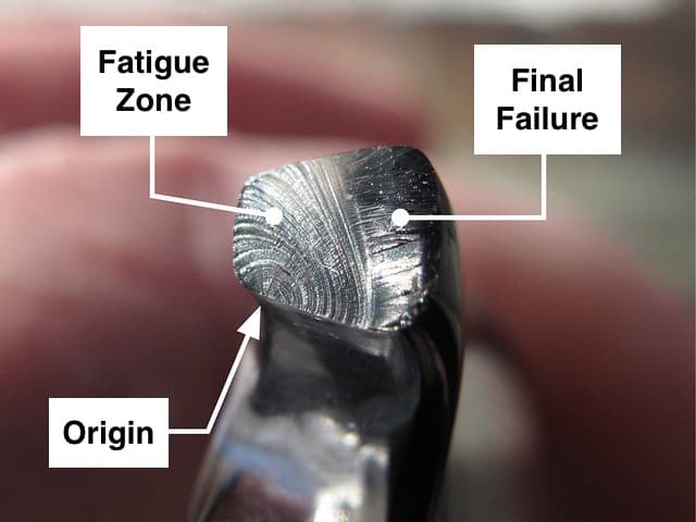
- A fatigue failure usually originates at a point of stress- concentration such as a sharp corner or notch or a weak section on the component(Origin of the fracture from the above figure), or at a metallurgical inclusion or flaw.
- Once nucleated, the crack propagates across the part under the cyclic or repeated stresses.
- During this stage of the fatigue process, clamshell or “beach” marks are created, as shown in above figure.
- Finally, the remaining section becomes so small that it can no longer support the load, and complete fracture occurs.
- Thus, there are usually two distinct types of surface areas that can be recognized:
- A smooth surface region due to the rubbing action between the open surface region as the crack propagates across the section.
- A rough surface area formed by the fracture when the load becomes too high for the remaining cross-section.
- In the above fatigue fracture image, the fatigue crack had propagated almost through the entire cross-section before the final rupture occurred.
Fatigue Testing with Rotating-Beam
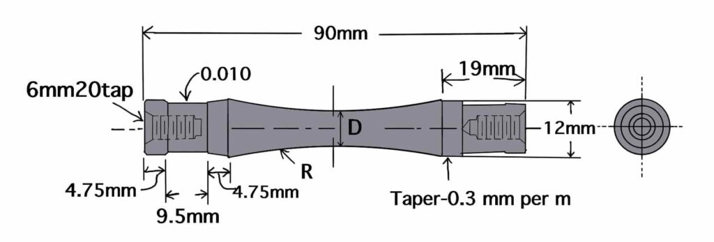
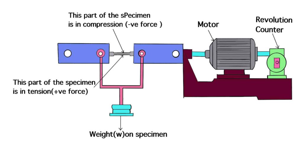
Many types of tests are used to determine the fatigue life of a material. The most commonly used small-scale fatigue test is the rotating-beam test in which a specimen is subjected to alternating compression and tension stresses of equal magnitude while being rotated. A sketch of the specimen for the R. R. Moore reversed bending fatigue test is. shown below.
- The surface of this specimen is carefully polished and tapered toward the center.
- During the testing of a fatigue sample by this apparatus, the centre of the specimen is actually undergoing tension on the lower surface and compression on the upper surface by the weight attached in the centre of the apparatus as exaggerated in above figure.
- Data from this test are plotted in the form of SN curves in which the stress S to cause failure is plotted against the number of cycles N at which failure occurs.
- Below Figure shows typical SN curves for high-carbon steel and a high-strength aluminium alloy.
- For the 2014-T6 Aluminium alloy, the stress to cause failure decreases as the number of cycles is increased.
- For the 1047 Carbon steel, there is first a decrease in fatigue strength as the number of cycles is increased and then there is leveling off in fatigue strength as the number of cycles is increased.
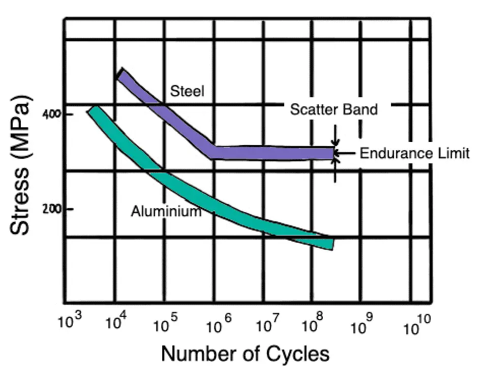
- This horizontal part of the SN plot is called the fatigue or endurance limit and lies between 106 and 1010 cycles.
- Many ferrous alloys exhibit an endurance limit that is about one-half their tensile strength.
- Non-ferrous alloys such as aluminum alloys do not have an endurance limit and may have fatigue strengths as low as one-third their tensile streng
What is fatigue life?
Fatigue life means the number of cycles of stress that a component can withstand before failure is known as Fatigue life. Check here how you can calculate the Fatigue life here.
Cyclic Stresses in Fatigue Failure of Material
the applied fatigue stress may vary greatly in real cases and in fatigue tests. Many different kinds of fatigue test methods used in industry and research involve axial, torsional, and flexural stresses.
We have shown the graphs of fatigue stress versus a number of fatigue cycles for three fatigue cycle tests.
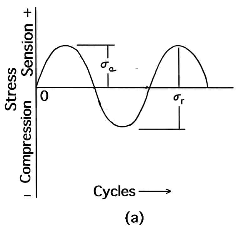
The above Cyclic stress graph shows a graph of stress versus fatigue cycles for a completely reversed stress cycle of a sinusoidal form. This graph is typical of that produced by a rotating shaft operating at a constant speed without overloads. The R. R. Moore reversed-bending fatigue machine shown above produces similar stress versus a number of fatigue cycles plots.
In this fatigue cycle, the maximum and minimum stresses are equal. By definition, the tensile stresses are considered positive and the compressive stresses negative, and the maximum stress has the highest numeric value and the minimum stress the lowest.
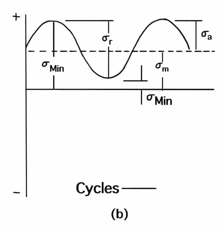
The above Cyclic stress graph shows a repeated stress cycle in which the maximum stress σmax and the minimum stress σmin are equal.
In this case, both maximum and minimum stresses are tensile, but .a repeated stress cycle can also have maximum and minimum stresses .of opposite sign, or both in compression. Finally, cyclic stress may vary randomly in amplitude and frequency, as shown in the below cyclic stress graph. In this case, there can be a spectrum of different fatigue graphs of stress versus cycles.
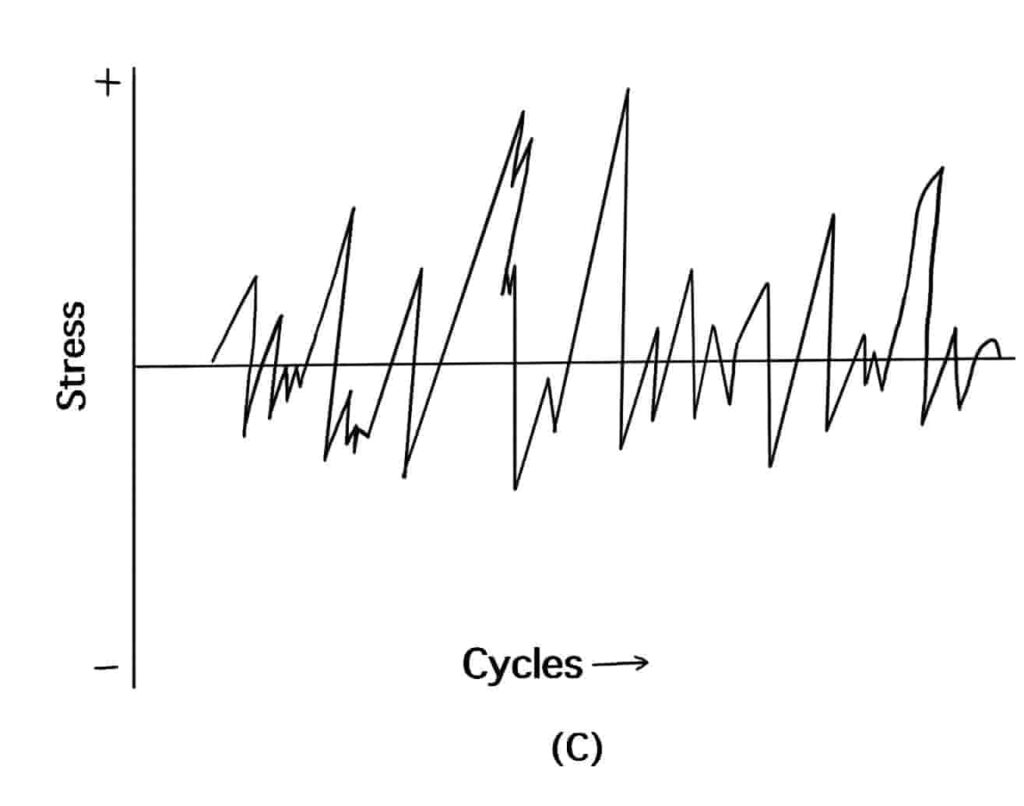
Fluctuating stress cycles are characterized by a number of parameters. Some of the most important ones are:
1. Mean stress σm is the algebraic mean of the maximum and minimum stress

2. Range of stress σr is the difference between σ max and a σ min
σr = σr max – σr min
3. Stress amplitude σa a is one-half the stress cycle
4. Stress ratio R is the ratio of minimum and maximum stresses.
r = σ min / σ max
Basic Structural Changes that Occur in a Ductile Metal in the Fatigue Process
When a specimen of a ductile homogeneous metal is subjected to cyclic stresses, the following basic structural changes occur during the fatigue process
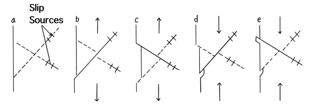
- Crack initiation: The early development of fatigue damage occurs.
- Slipband crack growth: Crack initiation occurs because plastic deformation is not a completely reversible- process. Plastic deformation in one direction and then in the reverse direction causes surface ridges and grooves called slipband extrusions and slipband intrusions to be created on the surface of the metal specimen as well as darriage within the metal along persistent slipbands . The surface irregularities and damage along the persistent slipbands cause cracks to form at or near the surface that propagate into the specimen along the planes subjected to high shear stresses. This is called stage I of fatigue crack growth, and the rate of the crack growth is in general very low (for example, 1010 m/cycle)
- Crack growth on planes of high tensile stress: During stage I the crack may grow in a polycrystalline metal only a few grain diameters before it changes its. direction to be perpendicular to the direction of the maximum tensile stress on the metal specimen. In this stage II of crack growth, a well-defined crack propagates at a relatively rapid rate (i.e. micrometers per cycle), and fatigue striations are created as the crack advances across the cross section of the metal specimen shown above. These striations are useful in fatigue failure analysis for determining the origin and direction of propagation of fatigue cracks.
- Ultimate ductile failure: Finally when the crack covers a suffiCient area so thatthe reinaining metal at’the cross section cannot. support the applied load, the sample ruptures by ductile failure.
Some Major Factors that affect the Fatigue Strength of a Metal
The fatigue strength of a metal or alloy is affected by factors other than the chemical composition of the metal itself. Some of the most important of these are:
- Stress concentration: Fatigue strength is greatly reduced by the presence of stress raisers such as notches, holes, keyways, or sharp changes in cross sections. For example, the fatigue failure shown in above figure started at the solid wire. Fatigue failures can be minimized by careful design to avoidstressraisers whenever possible.
- Surface roughness: In general the smoother the surface finish on the metal sample, the higher the fatigue Strength. Rough surfaces create stress raisers that facilitate fatigue crack formation.
- Surface condition: Since most fatigue failures priginate at the metal surface, any major change in. the surface condition will affect the fatigue strengfu bf the metal. For example, surface-hardening treatments for “steels, such as carburizing and. nitriding, which harden the surface, increase fatigue life. Decarburizing, onthe other hand, which softens “a heat-treated steel surface, lowers fatigue life. The introduction of a favorable compressive residual stresspattern on the metal surface also increases fatigue life.
- Environment: If a corrosive environment is present during the cyclic stress of a metal, the chemical attack greatly accelerates the rate at which fatigue cracks propagate. The combination of corrosion attack and cyclic stresses on a metal is known as corrosion fatigue.
Fatigue Crack Propagation Rate
Most fatigue data for metals and alloys for high-cycle fatigue. that is fatigue lives of greater than 104 to 105 cycles have been concerned with the nominal stress required to cause failure in a given number of cycles, that is SN curves such as those shown in the above SN curve.
However, for these tests smooth or notched specimens are usually used, and thus it is difficult to distinguish between fatigue crack initiation life and fatigue crack propagation life. Thus, test methods have been developed to measure fatigue life associated with preexisting flaws in a material.
Pre-existing flaws or cracks within a material component reduce or may eliminate the crack initiation part of the fatigue life of a component. Thus, the fatigue life of a component with preexisting flaws may be considerably shorter than the life of one without flaws. In this section, we will utilize fracture mechanics methodology to develop a relationship to predict fatigue life in a material with preexisting flaws and under stress-state conditions due to cyclic fatigue action.
Read more about Fatigue Crack Propagation Rate here
Difference between Endurance limit or Fatigue limit or Fatigue strength
Fatigue refers to the failure of the machine component due to repeated or cyclic loading. Whereas the fatigue strength or fatigue limit or Endurance limit is used to describe the material property that the cyclic load can be applied to the material without causing the failure.
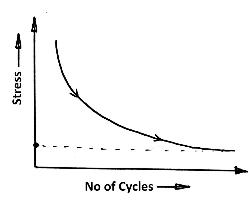
- Endurance limit ensures the number of cyclic loads that can be acceptable by the component before going to fail by limiting the stress values.
- See the graph between the Stress – No of Cycles (S-N curve)
- As the number of cycles increasing the Stress values for the material will decrease.
- At some point, the stress values can be constant. That means for the infinite number of cycles the limiting stress values will not be changed.
Endurance limit for the different materials
Endurance limit of steel = 0.5 × ultimate tensile strength of the steel
Endurance limit of Iron = 0.4 × ultimate tensile strength of the Iron
Read more about the Difference between Endurance limit or Fatigue limit here
Conclusion
The most important observation is that the maximum stresses caused the fatigue failure, in this case, are much less than the actual strength of the material (Yield stress limit). Fatigue failure is the most common failure occurring in the mechanical components. we can say over 90% of mechanical failures are fatigue failures. We have a project paper on Corrosion Fatigue Analysis of Medium Carbon Steel C45. Check it out.
Among the other material failures, Fracture failure, and fatigue failure and Creep failure are observed in the testing stage of prototypes. All these concepts are very important for every design engineer should have a deep understanding of.

Leave a Reply