An Optical Flat is a glass claimed to be extremely flat on one or both sides. it will be used with monochromatic light to determine the flatness of other objects with the help of optical interference.

The optical flat is the popular choice for measurement using the interferometry technique, a host of other instruments, popularly known as interferometers, are also available. An interferometer, in other words, is the extension of the optical flat method. While interferometers have long been the mainstay of dimensional measurement in physical sciences, they are also becoming quite popular in metrology applications. While they work according to the basic principle of an optical flat. They provide additional conveniences to the user. The mechanical design minimizes time-consuming manipulation. The instrument can be fitted with additional optical devices for magnification, stability, and high resolution. In recent times, the use of lasers has greatly extended the potential range and resolution of interferometers. Let us discuss the Optical flat in detail.
Optical Flat
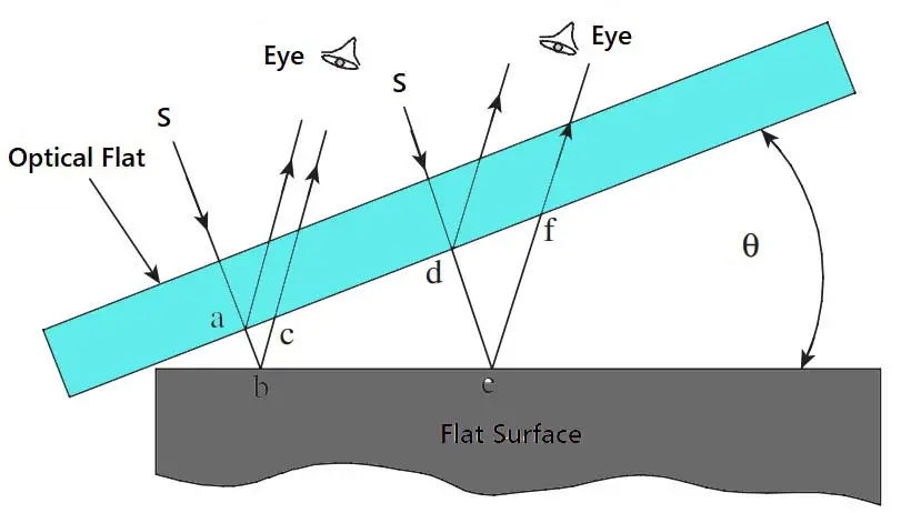
The most common interference effects are associated with thin transparent films or wedges bounded on at least one side by a transparent surface. Soap bubbles, oil films on water, and optical flats fall in this category. The phenomenon by which interference takes place is readily described in terms of an optical flat, as shown below figure.

- An optical flat is a disk of high-quality glass or quartz. The surface of the disk is ground and lapped to a high degree of flatness.
- Sizes of optical flats vary from 25 to 300mm in diameter, with a thickness ranging from 25 to 50mm.
- When an optical flat is laid over a flat reflecting surface, it orients at a small angle θ, due to the presence of an air cushion between the two surfaces. This is illustrated above figure.
- Consider a ray of light from a monochromatic light source falling on the upper surface of the optical flat at an angle.
- This light ray is partially reflected at point ‘a’.
- The remaining part of the light ray passes through the transparent glass material across the air gap and is reflected at point ‘b’ on the flat work surface.
- The two reflected components of the light ray are collected and recombined by the eye, having travelled two different paths whose length differs by an amount ‘abc’.
- If ‘abc’ = λ/2, where λ is the wavelength of the monochromatic light source, then the condition for complete interference has been satisfied.
- The difference in path length is one-half the wavelength, a perfect condition for total interference, as explained in the previous article Optical Interference.
- The eye is now able to see a distinct patch of darkness termed a fringe.
- Next, consider another light ray from the same source falling on the optical flat at a small distance from the first one.
- This ray gets reflected at points ‘d’ and ‘e’. If the length ‘def’ equals 3λ/2, then total interference occurs again and a similar fringe is seen by the observer.
- However, at an intermediate point between the two fringes, the path difference between two reflected portions of the light ray will be an even number of half wavelengths.
- Thus, the two components of light will be in phase, and a light band will be seen at this point.
To summarize, when light from a monochromatic light source is made to fall on an optical flat, which is oriented at a very small angle with respect to a flat reflecting surface, a band of alternate light and dark patches is seen by the eye. The below Figure illustrates the typical fringe pattern seen on a flat surface viewed under an optical flat.

In the case of a perfectly flat surface, the fringe pattern is regular, parallel, and uniformly spaced. Any deviation from this pattern is a measure of the error in the flatness of the surface being measured. Fringe patterns provide interesting insights into the surface being inspected. They reveal surface conditions like contour lines on a map.

| Fringe pattern | Surface condition |
| A | Block is nearly flat along its length. |
| B | Fringes curve towards the line of contact, showing that the surface is convex and high in the centre |
| C | The surface is concave and low in the centre. |
| D | The surface is flat at one end but becomes increasingly convex |
| E | The surface is progressively lower towards the bottom left-hand corner |
| F | There are two points of contact, which are higher compared to other areas of the block |
The above Figure illustrates typical fringe patterns, and the Table offers useful hints about the nature of surfaces corresponding to the patterns. Once we recognize surface configurations from their fringe patterns, it is much easier to measure the configurations.
Measurement using Optical Flats
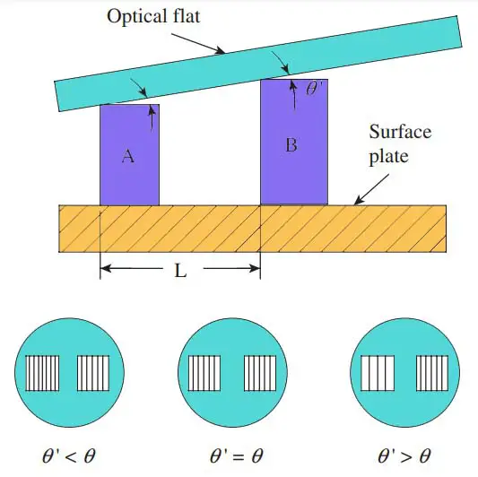
One of the obvious uses of an optical flat is to check the heights of slip gauge blocks. The slip gauge that is to be checked is kept alongside the reference gauge on a flat table. An optical flat is then placed on top of both gauges, as shown in the below figure.

- Let us assume that A is the standard reference gauge block while B is the gauge block that is being inspected.
- A monochromatic light source is used and the fringe patterns are observed with the help of a magnifying glass.
- It can be seen from the figure that the optical flat makes inclinations of q and q ‘ with the top surfaces of the two slip gauges. Ideally, the two angles should be the same.
- However, in most cases, the angles are different by virtue of the wear and tear of the surface of the slip gauge that is being inspected.
- This can easily be seen by looking at the fringe pattern that is formed on the two gauges, as seen from the magnified images.
- The fringes seen on both the gauges are parallel and same in number if both the surfaces are perfectly flat; otherwise, the number of fringes formed on the two gauges differs, based on the relationship between q and q ‘.
Now, let the number of fringes on the reference block be N over a width of l mm. If the distance between the two slip gauges is L and λ is the wavelength of the monochromatic light source, then the difference in height h is given by the following relation:
h = λLN/2l
This simple procedure can be employed to measure very small height differences in the range of 0.01–0.1mm. However, the accuracy of this method depends on the accuracy of the surface plate and the condition of the surfaces of the specimen on which the optical flat is resting.
It is difficult to control the ‘lay’ of the optical flat and thus orient the fringes to the best advantage. The fringe pattern is not viewed directly above, and the resulting obliquity can cause distortion and errors in viewing. A better way of conducting accurate measurement is to use an interferometer. While a variety of interferometers are used in metrology and physical sciences, two types are the NPL flatness interferometer and the Pitter–NPL gauge interferometer.
Conclusion
We have discussed what is an Optical flat in Interferometry with the construction, working principle and how to measure with an Optical Flat. Let us know what do you think about it in the comment section below.

Leave a Reply