Interferometry is nothing but optical interference to carry out precise measurements of very small linear dimensions. Pitter–NPL Gauge Interferometer is one of the interferometers in metrology used for determining actual lengths of slip gauges. We will discuss this Pitter–NPL Gauge Interferometer construction and working principle with help of a schematic diagram in this article.

As we mentioned above, the Pitter–NPL Gauge Interferometer is used to determine the actual lengths of slip gauges. Since the measurement calls for a high degree of accuracy and precision, the instrument should be used under highly controlled physical conditions. It is recommended that the system be maintained at an ambient temperature of 20°C, and a barometric pressure of 760mmHg with a water vapour pressure of 7mm, and contain 0.33% by volume of carbon dioxide.
Construction of Pitter–NPL Gauge Interferometer
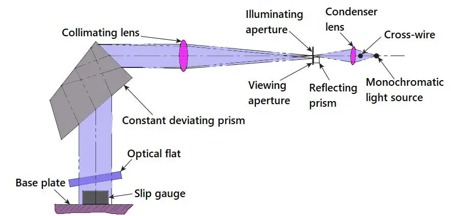
The optical system of the Pitter–NPL interferometer is shown below figure.

- Light from a monochromatic source (the preferred light source is a cadmium lamp) is condensed by a condensing lens and focused onto an illuminating aperture.
- This provides a concentrated light source at the focal point of a collimating lens.
- Thus, a parallel beam of light falls on a constant deviation prism.
- This prism splits the incident light into light rays of different wavelengths and hence different colours.
- The user can select a desired colour by varying the angle of the reflecting faces of the prism relative to the plane of the base plate.
- The prism turns the light by 90° and directs it onto the optical flat.
- The optical flat can be positioned at a desired angle by means of a simple arrangement.
- The slip gauge that is to be checked is kept right below the optical flat on top of the highly flat surface of the base plate.
- The lower portion of the optical flat is coated with a film of aluminium, which transmits and reflects equal proportions of the incident light.
- The light is reflected from three surfaces, namely the surface of the optical flat, the upper surface of the slip gauge, and the surface of the base plate.
- Light rays reflected from all the three surfaces pass through the optical system again; however, the axis is slightly deviated due to the inclination of the optical flat.
- This slightly shifted light is captured by another prism and turned by 90°, so that the fringe pattern can be observed and recorded by the user.
Working Principle of Pitter–NPL Gauge Interferometer
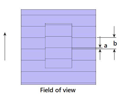
The typical fringe pattern observed is shown below figure. Superimposition of the fringes corresponding to the upper surface of the slip gauge upon those corresponding to the base plate’s surface is shown in the figure below.

It can be seen that the two sets of fringes are displaced by an amount concerning each other. The value of a varies depending on the colour of the incident light. The displacement a is expressed as a fraction of the fringe spacing b, which is as follows:
f = a/b
The height of the slip gauge will be equal to a whole number of half wavelengths, n, plus the fraction a/b of the
half wavelengths of the radiation in which the fringes are observed.
Therefore, the height of the slip gauge, H = n (λ/2) + (a/b) × (λ/2),
- where n is the number of fringes on the slip gauge surface, λ is the wavelength of light, and a/b is the observed fraction.
- However, practitioners of industrial metrology are not happy with the values thus obtained.
- The fraction readings are obtained for all three colours of cadmium, namely red, green, and violet.
- For each of the wavelengths, fractions a/b are recorded.
- Using these fractions, a series of expressions are obtained for the height of the slip gauge.
- These expressions are combined to get a general expression for gauge height.
The Pitter–NPL gauge interferometer is provided with a slide rule, in which the wavelengths of red, green, and violet are set to scale, from a common zero. This provides a ready reckoner to speed up calculations.
Conclusion
We have discussed the Pitter–NPL Gauge Interferometer with the construction and working principle. Let us know what do you think about this in the comment section below.

Leave a Reply