A rocker’s arm is a valvetrain component that typically transfers the motion of a push rod to the corresponding intake/exhaust valve. The rocker’s arm is used to actuate the inlet and exhaust valve motion as directed by the cam and follower. Let us see if we can design Rocker’s Arm for Exhaust Valve for a petrol Engine.
Since rocker’s arms are used to control both the intake and exhaust valves, swapping high-ratio rocker arms onto an engine increases both the intake-air command and the exhaust-scavenging potential.
In an Internal Combustion engine, a rocker’s arm is a valvetrain component that typically transfers the motion of a pushrod to the corresponding intake/exhaust valve. The rocker’s arm is typically located between the intake valve and the exhaust valve and the pushrod. This pushrod is used to push and pull the arm. This pushing action of the pushrod “rocks” the rocker’s arm up and down. For this reason, the intake and exhaust valves of the engine combustion chamber, which has a camshaft under the engine, are opened and closed.
In the previous articles, we have different Mechanical Levers.
- Hand Lever (Hand Brake)
- Foot Lever (Brakes pedal, Foot pump Lever)
- Cranked Lever (Hoisting Winches)
- Lever Safety Valve
- Bell Crank Lever
Procedure for Designing Rocker’s Arm
A rocker arm for operating the exhaust valve is shown in the following. In designing a rocker’s arm, the following procedure may be followed:
- The rocker’s arm is usually of I-section. Due to the load on the valve, it is subjected to a bending moment. In order to find the bending moment, it is assumed that the arm of the lever extends from the point of application of the load to the center of the pivot which acts as a fulcrum of the rocker arm. This assumption results in a slightly stronger lever near the boss.
- The ratio of the length to the diameter of the fulcrum and roller pin is taken as 1.25. The permissible bearing pressure on this pin is taken from 3.5 to 6 N/mm2.
- The outside diameter of the boss at the fulcrum is usually taken as twice the diameter of the pin at the fulcrum. The boss is provided with a 3 mm thick phosphor bronze bush to take up wear.
- Oneendoftherockerarmhasaforkedendtoreceivetheroller.Therolleriscarriedonapin is free to revolve in an eye to reduce wear. The pin or roller is not provided with a bush because after sufficient service the roller has to be discarded due to wear at the profile.
- The outside diameter of the eye at the forked end is also taken as twice the diameter of the pin. The diameter of the roller is taken slightly larger (at least 3 mm more) than the diameter of the eye at the forked end. The radial thickness of each eye of the forked end is taken as half the diameter of the pin. Some clearance, about 1.5 mm, must be provided between the roller and the eye at the forked end so that the roller can move freely. The pin should, therefore, be checked for bending.
- The other end of the rocker’s arm (i.e.tappet end)is made circular to receive the tappet which is a stud with a lock nut. The outside diameter of the circular arm is taken as twice the diameter of the stud. The depth of the section is also taken equal to twice the diameter of the stud.
With this procedure, let us design Rocker’s Arm for Exhaust Valve for a petrol Engine.
Problem Statement: For operating the exhaust valve of a petrol engine, the maximum load required on the valve is 5000 N. The rocker’s arm oscillates around a pin whose center line is 250 mm away from the valve axis. The two arms of the rocker are equal and make an included angle of 160°. Design the rocker arm with the fulcrum if the tensile stress is 70 MPa and the bearing pressure is 7 N/mm2. Assume the cross-section of the rocker’s arm is rectangular.
A rocker arm for operating the exhaust valve is shown in the following figure
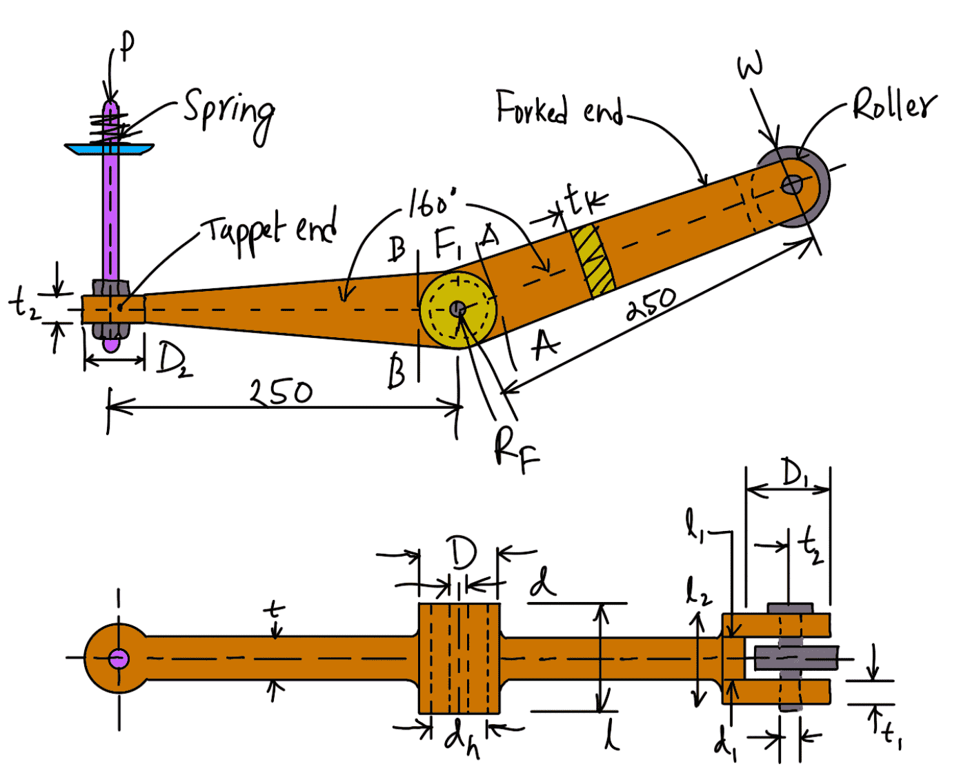
All Dimensions are in mm.
The known design parameter of the Rocker’s Arm for the Exhaust Valve is
W = 5000N
θ = 160°
σt = 70MPa =70N/mm2
pb =7 N/mm2
First of all, let us find out the reaction at the fulcrum pin.
Let
RF = Reaction at the fulcrum pin.
Since the two arms of the rocker are equal, therefore the load at the two ends of the arm is equal i.e. W = P = 5000 N.
We know that

Design of Fulcrum for Rocker’s Arm
Let
d = Diameter of the fulcrum pin,
l = Length of the fulcrum pin = 1.25 d
Considering the bearing of the fulcrum pin. We know that load on the fulcrum pin (RF),
9850 = d × l × pb
9850 = d × 1.25 d × 7
9850 = 8.75 d2
d2 = 9850 / 8.75
d2 = 1126
d = 33.6
The diameter of the fulcrum pin is d = 35mm.
Length of the fulcrum pin l = 1.25 d = 1.25 × 35 = 43.75 let us say 45mm.
Now let us check the average shear stress induced in the pin. Since the pin is in double shear, therefore load on the fulcrum pin (RF),
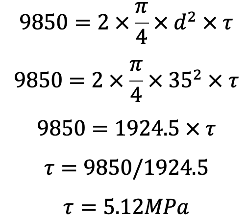
The induced shear stress is quite safe.
Now external diameter of the boss,
D = 2d = 2 × 35 = 70mm
Assuming a phosphor bronze bush 3 mm thick, the internal diameter of the hole in the lever,
dh = d + 2 × 3 = 35 + 6 = 41mm
Now let us check the induced bending stress for the section of the boss at the fulcrum which is shown in the following figure.
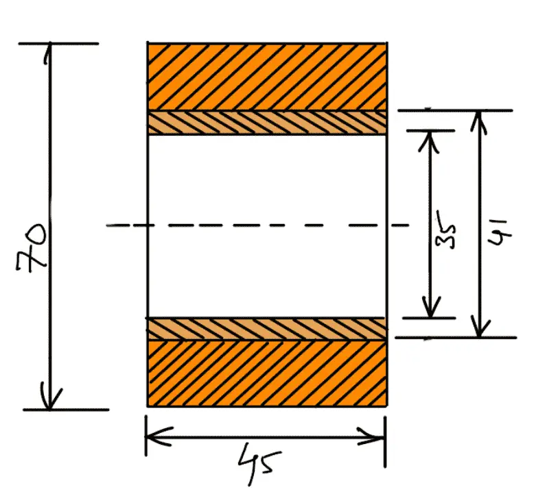
The bending moment in this section
= W × 250
= 5000 × 250 N-mm
= 1250 × 103 N-mm
Section modulus,

Induced bending stress,

Since the induced bending stress is less than the permissible value of 70 MPa, therefore it is safe.
Design for forked end for Rocker’s Arm
Let
d1 = Diameter of the roller pin,
l1 = Length of the roller pin = 1.25 d1
Considering the bearing of the roller pin. We know that load on the roller pin (W),
5000 = d1 ×l1 ×pb
5000 = d1 × 1.25d1 × 7
5000 = 8.75(d1)2
(d1)2 = 5000/8.75
(d1)2 = 571.4
d1 = 24mm
The diameter of the roller pin d is 24mm.
Length of the roller pin l = 1.25 d1 = 1.25 × 24 = 30mm
Let us now check the roller pin for induced shearing stress. Since the pin is in double shear, therefore load on the roller pin (W),
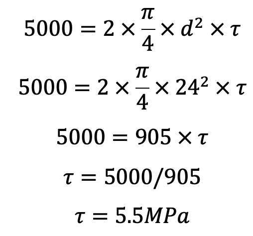
This induced shear stress is quite safe.
The roller pin is fixed in the eye and the thickness of each eye is taken as half the length of the roller pin.
The thickness of each eye,

Let us now check the induced bending stress in the roller pin. The pin is neither simply supported in the fork nor rigidly fixed at the end. Therefore the common practice is to assume the load distribution as shown in the following figure.
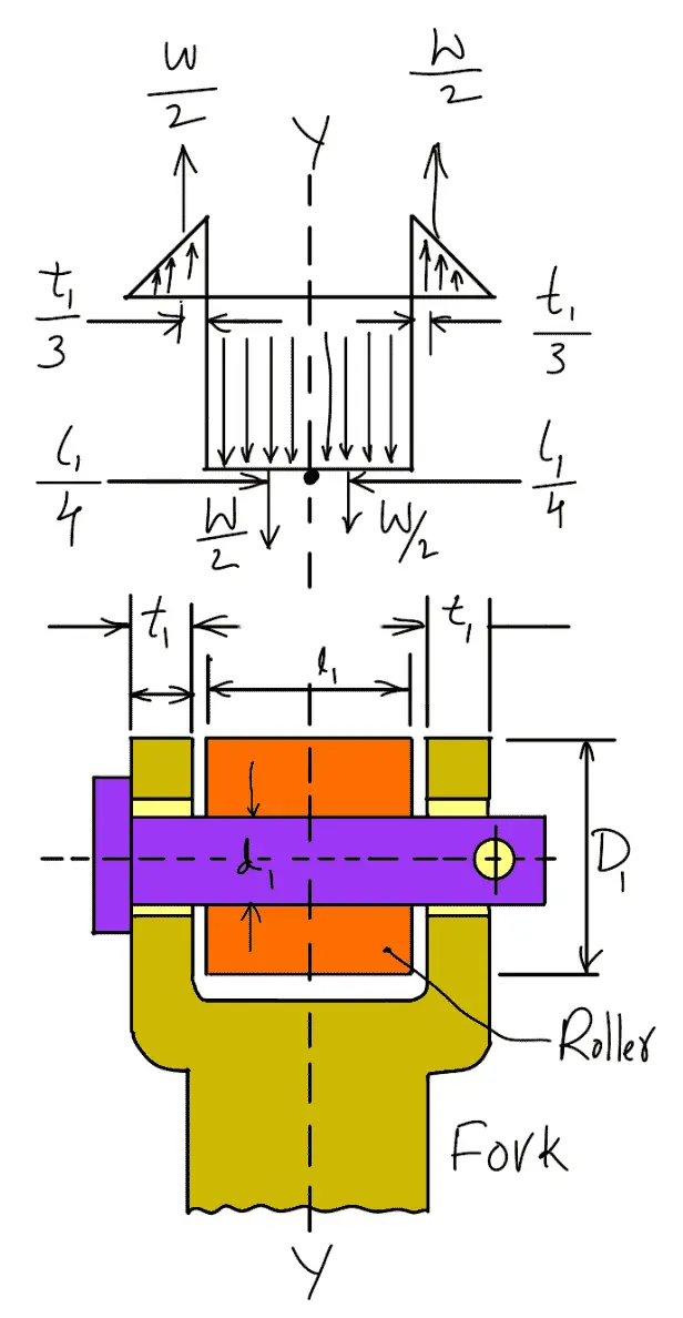
The maximum bending moment will occur at Y-Y.
Neglecting the effect of clearance, we have Maximum bending moment at Y–Y,
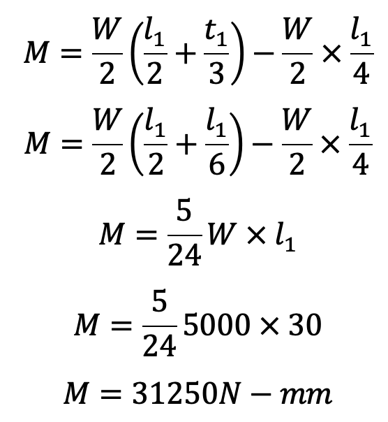
and section modulus of the pin,

Bending stress induced in the pin

The bending stress induced in the pin is within the permissible limit of 70 MPa.
Since the radial thickness of the eye (t2) is taken as d1 / 2, therefore the overall diameter of the eye,
D1 = 2d1 = 2 × 24 = 48mm
The outer diameter of the roller is taken slightly larger (at least 3 mm more) than the outer diameter of the eye.
In this design case, 54 mm outer diameter of the roller will be sufficient.
Providing a clearance of 1.5 mm between the roller and the fork on either side of the roller, we have
l2 = l1 + 2 × t1 + 2 × 1.5 = 30 + 2 × 15 + 3 = 48mm
Design of Lever Arm
The cross-section of the lever arm is obtained by considering the bending of the sections just near the boss of the fulcrum on both sides, such as sections A-A and B-B.
Let
t = Thickness of the lever arm which is uniform throughout.
B = Width or depth of the lever arm which varies from the boss diameter of the fulcrum to the outside diameter of the eye (for the forked end side) and from the boss diameter of the fulcrum to thickness t2 (for the tappet or stud end side).
Now bending moment on sections A-A and B-B,
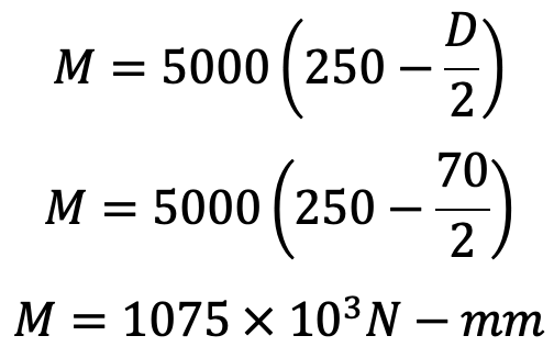
and section modulus at A-A and B-B,

We know that bending stress (σb),
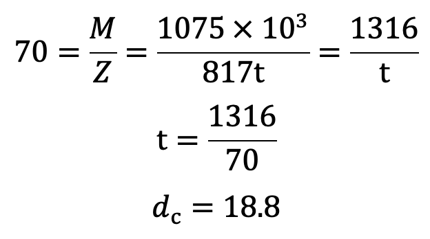
The Thickness of the lever arm which is uniform throughout is t = 20mm.
Design for Tappet Screw
The adjustable tappet screw carries a compressive load of 5000 N. Assuming the screw is made of mild steel for which the allowable compressive stress (σc) may be taken as 50 N/mm2.
Let
dc = Core diameter of the screw.
We know that load on the tappet screw (W),
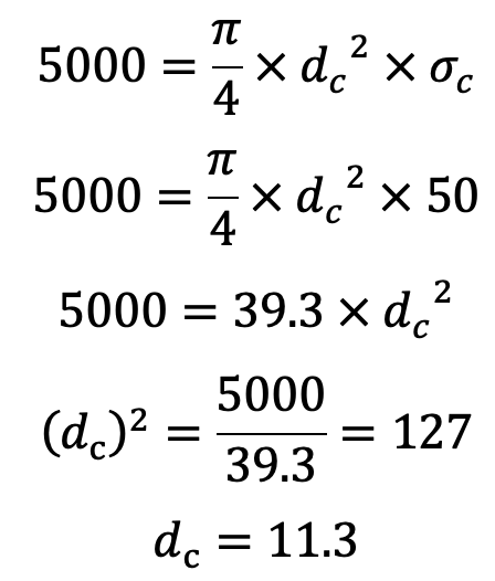
and the outer or nominal diameter of the screw,
d = dc/0.84 = 11.3/0.84 = 13.5
Let us take the Core diameter of the screw as 14mm.
We shall use a 14 mm stud and it is provided with a lock nut. The diameter of the circular end of the lever arm (D2) and its depth (t2) is taken twice the diameter of the stud.
D2 = 2 × 14 = 28mm
t2 = 2 × 14 = 28mm
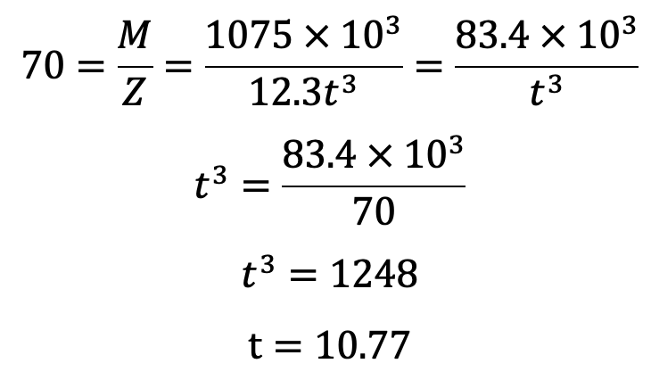
If the lever arm is assumed to be of I-section with proportions as shown in the following figure at A-A and B-B,
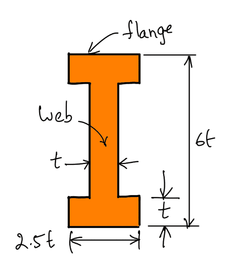
then section modulus,

We know that the maximum bending moment at A-A and B-B,
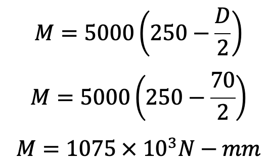
Bending stress (σb),
Let us take t as 12mm.
We have assumed that width of the flange = 2.5 t = 2.5 × 12 = 30mm
Depth of the web = 4t = 4 × 12 = 48mm
Depth of the section = 6 t = 6 × 12 = 72mm
Normally thickness of the flange and web is constant throughout whereas the width and the depth is tapered.
This is how you can design Rocker’s Arm for Exhaust Valve in a petrol engine.

Leave a Reply