A Mechanical Lever is a rigid rod or bar capable of turning about a fixed point called a fulcrum. It is used as a machine to lift a load by the application of a small effort. Lever Safety Valve is used to maintain a constant safe pressure inside the boiler. When the pressure inside the boiler increases the safe value, the excess steam blows off through the valve automatically. Let us discuss how we can design a Lever Safety Valve with the same mechanical lever principle.
History of Lever
In ancient Egypt circa 4400 BC, a foot pedal was used for the earliest horizontal frame loom. Another device that used the principle of the lever was the swape, or shaduf, a long lever pivoted near one end with a platform or water container hanging from the short arm and counterweights attached to the long arm. This device was used in Egypt and India for raising water and lifting soldiers over battlements as early as 1500 BC.

A balance beam for weighing, consisting of a bar pivoted at its center and weights that were hung on one end to balance the object being weighed on the other end, was probably used in Egypt around 5000 BC.
Introduction to Lever
A lever is a rigid rod or bar capable of turning about a fixed point called a fulcrum. It is used as a machine to lift a load by the application of a small effort. The ratio of load lifted to the effort applied is called Mechanical Advantage.
Sometimes, a lever is merely used to facilitate the application of force in a desired direction. A lever may be straight or curved and the forces applied on the lever (or by the lever) may be parallel or inclined to one another. The principle on which the lever works is the same as that of moments.
Consider a straight lever with parallel forces acting in the same plane as shown in the following figure.
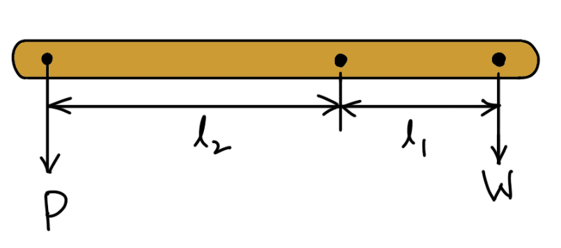
- The points A and B through which the load and effort are applied are known as load and effort points respectively.
- F is the fulcrum about which the lever is capable of turning.
- The perpendicular distance between the load point and fulcrum (l1) is known as the load arm.
- The perpendicular distance between the effort point and fulcrum (l2) is called the effort arm.
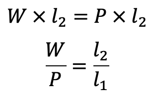
According to the principle of moments,
Mechanical Advantage
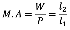
The ratio of the effort arm to the load arm i.e. l2 / l1 is called leverage.
A little consideration will show that if a large load is to be lifted by a small effort, then the effort arm should be much greater than the load arm. In some cases, it may not be possible to provide a lever with a large effort arm due to space limitations.
Therefore in order to obtain great leverage, compound levers may be used. The compound levers may be made of straight pieces, which may be attached to one another with pin joints. The bell-cranked levers may be used instead of a number of jointed levers. In a compound lever, the leverage is the product of leverages of various levers.
Lever Safety Valve
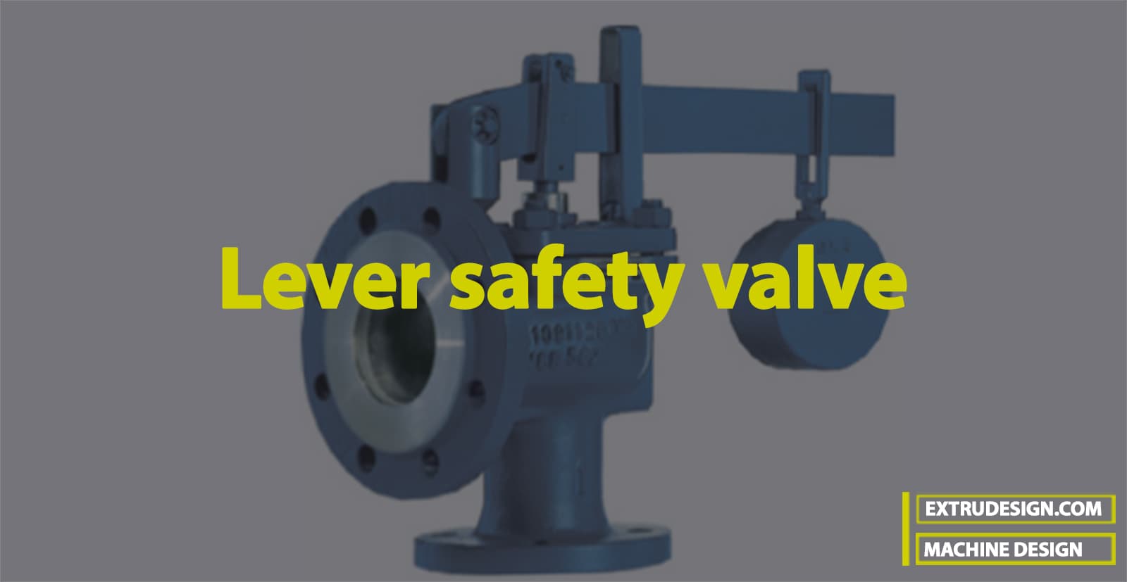
A lever safety valve is shown in the following images for reference.
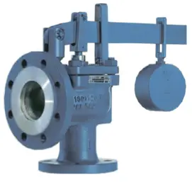
It is used to maintain a constant safe pressure inside the boiler. When the pressure inside the boiler increases the safe value, the excess steam blows off through the valve automatically. The valve rests over the gunmetal seat which is secured to a casing fixed upon the boiler. One end of the lever is pivoted at the fulcrum F by a pin to the toggle, while the other end carries the weights. The valve is held on its seat against the upward steam pressure by the force P provided by the weights at B. The weights and their distance from the fulcrum are so adjusted that when the steam pressure acting upward on the valve exceeds the normal limit, it lifts the valve and the lever with its weights. The excess steam thus escapes until the pressure falls to the required limit.
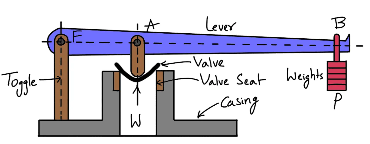
The lever may be designed in a similar way as discussed earlier for the Hand lever, Foot lever, and Cranked Lever.
The maximum steam load (W), at which the valve blows off, is given by
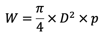
where
D = Diameter of the valve
p = Steam pressure
Lever Safety Valve Design
Let us design A lever-loaded safety valve that is 70 mm in diameter and is to be designed for a boiler to blow off at a pressure of 1 N/mm2 gauge. Design a suitable mild steel lever of rectangular cross-section using the Permissible Tensile stress = 70 MPa; Permissible Shear stress = 50 MPa; Permissible Bearing pressure intensity = 25 N/mm2. The pin is also made of mild steel. The distance from the fulcrum to the weight of the lever is 880 mm and the distance between the fulcrum and pin connecting the valve spindle links to the lever is 80 mm.
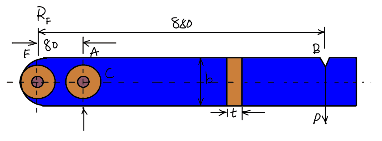
The known design parameters for the Lever Safety Valve are
D = 70 mm
p = 1 N/mm2
σt = 70 MPa = 70 N/mm2
τ = 50 MPa = 50N/mm2
pb = 25N/mm2
FB = 880mm
FA = 80mm
We know that the maximum steam load at which the valve blows off,

…. equation (i)
Taking moments about the fulcrum F, we have
P × 880 = 3850 × 80
P × 880 = 308 × 103
P = 308 × 103/880
P = 350N
Since the load (W) and the effort (P) in the form of dead weight are parallel and opposite, therefore reaction at F,
R = W-P
R = 3850-350
R = 3500N
This reaction will act vertically downward as shown in the above schematic diagram.
First of all, let us find the diameter of the pin at A from bearing considerations.
Let
dp = Diameter of the pin at A
lp = Length of the pin at A = 1.25 dp
∴ Bearing area of the pin at A = dp × lp = 1.25 (dp)2
and load on the pin at A = Bearing area × Bearing pressure
W = 1.25 (dp)2 pb
W = 1.25 (dp)2 25
W = 31.25 (dp)2
…. equation (ii)
Since the load acting on the pin at A is W = 3850 N, therefore from equations (i) and (ii), we get
31.25 (dp)2 = 3850
(dp)2 = 3850/31.25
(dp)2 = 123.2
dp = 11.1
And
lp = 1.25 dp
lp = 1.25 × 12
lp = 15mm
Let us now check the pin for shearing. Since the pin is in double shear, therefore load on the pin at A (W),
3850 = 2 × π/4 × (dp)2 τ
3850 = 2 × π/4 × (12)2 τ
3850 = 226.2τ
τ = 3850 / 226.2
τ = 17.02 N/mm2
τ = 17.02 MPa
This value of shear stress is less than the permissible value of 50 MPa, therefore the design for the pin at A is safe. Since the load at F does not very much differ with the load at A, therefore the same diameter of the pin may be used at F, in order to facilitate the interchangeability of parts.
∴ Diameter of the fulcrum pin at F = 12 mm
A gun metal bush of 2 mm thickness is provided in the pin holes at A and F in order to reduce wear and to increase the life of the lever.
∴ Diameter of hole at A and F = 12 + 2 × 2 =16mm
The outside diameter of the boss = 2 × Diameter of hole = 2 × 16 = 32mm
Now let us find out the cross-section of the lever considering the bending moment near the boss at A.
Let
t = Thickness of the lever
b = Width of the lever.
Bending moment near the boss at A i.e. at point C,
M = P × BC
M = P (BF – AF – AC)
M = 350 (880 – 80 – 16)
M = 277200 N-mm

We know that the bending stress (σb)

t3 = 104 × 103 / 70
t3 = 1.5 × 10³
t = 11.4
And
b = 4t
b = 4×12
b = 48mm
Now let us check for the maximum shear stress induced in the lever. From the shear force diagram, as shown in the following diagram, we see that the maximum shear force on the lever is (W – P) i.e. 3500 N.
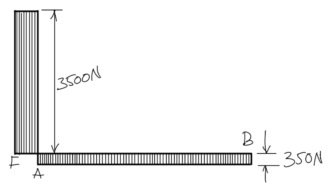
Maximum shear stress-induced,

Since this value of maximum shear stress of 6.07 Mpa is much below the permissible shear stress of 50 MPa, therefore, the design for the lever is safe.
Again checking for the bending stress induced at the section passing through the center of the hole at A. The section at A through the center of the hole is shown in the following figure.
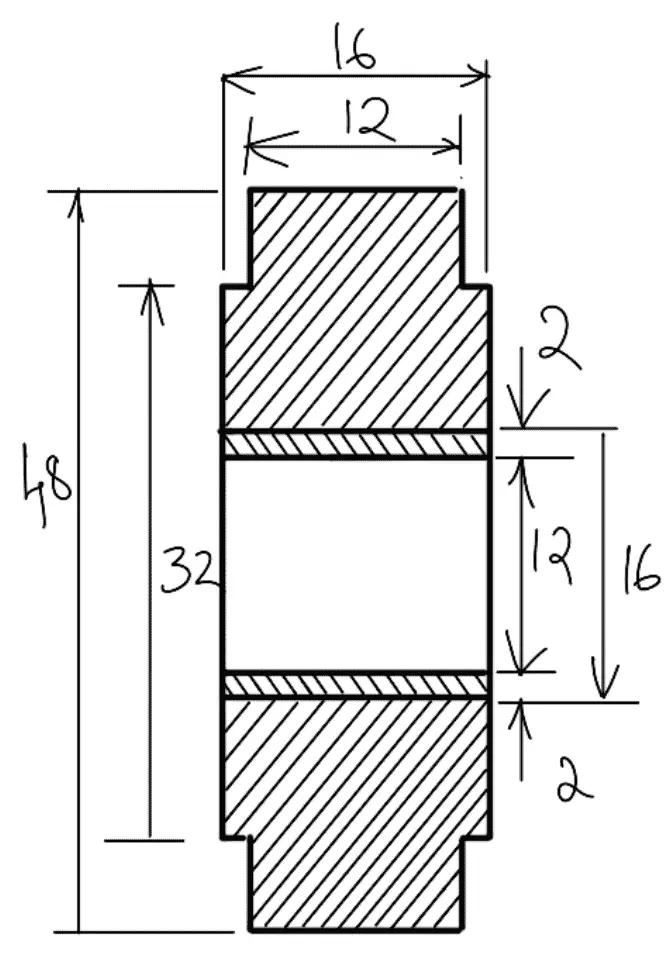
All Dimensions are in mm
∴ The maximum bending moment at the center of the hole at A,
M = 350(880–80)
M = 280 × 103 N-mm

Maximum bending stress induced,

Since this maximum stress is below the permissible value of 70 MPa, therefore the design in safe.
This is all about the Lever Safety Valve design. In addition, we have discussed different Mechanical Levers as follows already.
- Hand Lever (Hand Brake)
- Foot Lever (Brakes pedal, Foot pump Lever)
- Cranked Lever (Hoisting Winches)
- Bell Crank Lever
- Rocker’s Arm for the exhaust valve
Let us know what you think about this article in the comment section below.

Leave a Reply