We have discussed the different types of screw fasteners in the previous article, In every screwed joint these screwed fasteners will be tightened with torque or load which they can withstand. In order to know how much load we can apply, we must understand how much amount of stress it can bear in the screwed joint. Let us discuss how to calculate such stress in bolts or screws.
Let us assume that the screwed joint is under static loading and the screw is experiencing stress due to the static loading. Following are the different types of stresses are induced in the screwed fasteners.
- Initial stresses due to screwing up forces
- Stresses due to external forces
- Stress due to combination of stresses by screwing up and external Forces
We will discuss these stresses in a detailed manner and then we will calculate the stress in the bolts.
1. Initial stresses due to screwing up forces
When the screw or bolt is tightened up then there will be much different stress will be induced. The main stresses are identified as
i. Tensile stress due to stretching of the bolt
ii. Torsional shear stress caused by the frictional resistance of the threads during its tightening
iii. Shear stress across the threads
iv. Compression or crushing stress on threads
v. Bending stress if the surfaces under the head or nut are not perfectly parallel to the bolt axis
i. Tensile Stress due to Stretching of Bolt
The Bolts are designed with very large safety factors in order to account for the indeterminate stresses. No stress can be accurately determined, so it is necessary to maintain enough safety margin to avoid any unpredictable failures.
Based on experiments, The initial tension in a bolt may be found by the relation
Pi = 2840 d N
Where
Pi = Initial tension in a bolt, and
d = Nominal diameter of bolt (in mm)
This relation is tested for the fluid-tight joints for the application like steam engine cylinder cover joints, and engine sum joints, etc.
One important note for the fluid-tight joints, the smaller the bolt diameter, there is the higher risk of failure while tightening the bolt. To avoid such failures, we do not use the smaller bolt diameter which is less than the M16 or M18 bolts. That is the reason the smaller bolts are not permitted in making fluid-tight joints.
If we do not need that much a fluid-tight joint, then we can use half the value of the above factor for the joints to calculate the initial tension in the bolts.
Pi = 1420 d N
If the bolt is not initially stressed, then the maximum safe axial load which may be applied to it is given by
P = Permissible stress × Cross-sectional area at bottom of the thread (i.e. stress area) ……Eqn(1)
The stress area may be obtained from the Table mentioned here!
Or you can calculate it from the following relation.

Where
dp = Pitch diameter
dc = Core or minor diameter
ii. Torsional shear stress caused by the frictional resistance of the threads during its tightening
We know the torsion equation
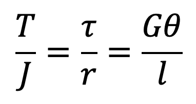
The torsional shear stress caused by the frictional resistance of the threads during its tightening may be obtained by using the above torsion equation.
We know that
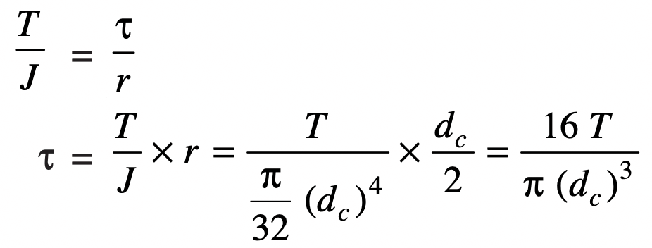
Where
τ = Torsional Shear stress
T = Applied Torque
dc = Core or minor diameter
The torsional twisting moment(T) may be increased due to the soaring of the threads on the bolt or the threads inside the nut.
This soaring may be occurred due to repeated tightening of the bolt or nut and unscrewing of the nut. This has been observed with experiments and testing.
iii. Shear stress across the threads
The Thread shear stress is represented with the τs.
The average shearing stress across the threads for the screw (τs) is obtained by using the following relation
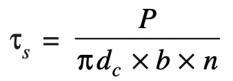
Where
b = Width of the thread section at the root
The average thread shearing stress for the nut also can be calculated with the following relation
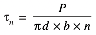
Where
d = Major diameter
iv. Compression or crushing stress on threads
The compression or crushing stress between the threads (σc) may be obtained by using the following relation

where
d = Major diameter
dc = Core or minor diameter
n = Number of threads in engagement
v. Bending stress if the surfaces under the head or nut are not perfectly parallel to the bolt axis
When the Bolt is subjected to bending loading, then it is necessary to take the bending stress into consideration.
The bolt bending may happen When the outside surfaces of the parts to be connected are not parallel to each other, then the bolt will be subjected to bending action.
The bending stress (σb) induced in the shank of the bolt is given by
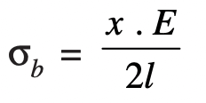
where
x = Difference in height between the extreme corners of the nut or head
l = Length of the shank of the bolt
E = Young’s modulus for the material of the bolt
These are the different types of initial stress that we need to consider while designing or choosing a bolt for an application.
Let us solve an example problem so that we can understand how to determine the safe load for the bolt.
Example problem
Determine the safe tensile load for a bolt of M 30, assuming safe tensile stress of 42 MPa
Answer:
Given data
Bolt diameter d=30mm
Safe tensile stress σt = 42MPa = 42 N/mm2
For the M30 bolt size the stress is is 561 mm2 (This value taken from coarse threads table here!)
Safe tensile load = Stress area × σt
Safe tensile load = 561×42 = 23562N
Safe tensile load = 23.562kN
In this example problem, we have assumed that the bolt is not initially stressed
This is the way you can calculate any of the above 5 types of safe stresses or permissible loads based on the given type of stress.
You can solve the following one more problem on your own and let us know in the comment section below.
Exercise problem
Two machine parts are fastened together tightly by means of a 24 mm tap bolt. If the load tending to separate these parts is neglected, find the stress that is set up in the bolt by the initial tightening.
Solve it and let us know the answer in the comment section below.
2. Stresses due to external forces
Majorly there will be two external forces that might cause failure due to the external loads on the bolt. And the combination of these is also the most common scenario for the bolt joints.
a. Tensile Stress
b. Shear stress
c. Combined Tensile stress and Shear Stress
a. Tensile Stres
The bolts, studs, and screws usually carry a load in the direction of the bolt axis which induces tensile stress in the bolt.
Let
dc = Root or core diameter of the thread
σt = Permissible tensile stress for the bolt material.
We know that external load applied is given in the following

Now from Table, the value of the nominal diameter of bolt corresponding to the value of dc may be obtained
or

If the external load is taken up by a number of bolts, then

In case the standard table is not available, then for coarse threads, dc = 0.84 d, where d is the nominal diameter of the bolt.
b. Shear Stress
- Sometimes,the bolts are used to prevent the relative movement of two or more parts, as in case of flange coupling, then the shear stress is induced in the bolts.
- The shear stresses should be avoided as far as possible.
- It should be noted that when the bolts are subjected to direct shearing loads, they should be located in such a way that the shearing load comes upon the body (i.e. shank) of the bolt and not upon the threaded portion.
- In some cases, the bolts may be relieved of shear load by using shear pins.
- When a number of bolts are used to share the shearing load, the finished bolts should be fitted to the reamed holes.
Let
d = Major diameter of the bolt
n = Number of bolts.
The Shearing load carried by the bolts can be calculated from the following relation

c. Combined tension and shear stress
When the bolt is subjected to both tension and shear loads, as in the case of coupling bolts or bearing, then the diameter of the shank of the bolt is obtained from the shear load and that of the threaded part from the tensile load.
A diameter slightly larger than that required for either shear or tension may be assumed and stresses due to combined load should be checked for the following principal stresses.
Maximum principal shear stress can be calculated from the following relation

and the maximum principal tensile stress calculated from the following relation

These tensile stress and the shear stresses should not exceed the safe permissible values of stresses.
Let us solve an example problem to understand how to design a bolt or choose a bolt for a safe load with help of the above formulas.
Problem Statement 3: Two shafts are connected by means of a flange coupling to transmit the torque of 25 N-m. The flanges of the coupling are fastened by four bolts of the same material at a radius of 30 mm. Find the size of the bolts if the allowable shear stress for the bolt material is 30 MPa.
Answer:
Given Data
Transmitted torque T = 25N-m = 25×103 N-mm
Number of bolts n = 4 bolts at a radius of(Rp) = 30mm
Shear stress τ = 30MPa = 30N/mm2
We know that the shearing load carried by flange coupling is given by
Ps = T/Rp
Ps = 25×103/30 = 833.3 N
From the above shear stress formula

833.3 = (π/4)×(dc)2×30×4
833.3 = 94·26 ×(dc)2
(dc)2 = 8.84
dc = 2.97mm
Where dc = Core diameter of the bolt
From Table (coarse series), we find that the standard core diameter of the bolt is 3.141 mm and the corresponding size of the bolt is M4.
This is how you can choose the bolt size by calculating the stress in bolts and picking it from the standards bolts list.
You can solve the following one more problem on your own and let us know in the comment section below.
Problem Statement 4: A lever-loaded safety valve has a diameter of 100 mm and the blow-off pressure is 1.6 N/mm2. The fulcrum of the lever is screwed into the cast iron body of the cover. Find the diameter of the threaded part of the fulcrum if the permissible tensile stress is limited to 50 MPa and the leverage ratio is 8.
Solve it and let us know the answer in the comment section below.
3. Stress due to combination of stresses by screwing up and external Forces
The resultant axial load on a bolt depends upon the following factors :
- The initial tension due to tightening of the bolt,
- The extenal load, and
- The relative elastic yielding (springiness) of the bolt and the connected members.
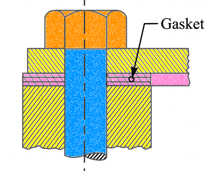
When the connected members are very yielding as compared with the bolt, which is a soft gasket, as shown in the above figure, then the resultant load on the bolt is approximately equal to the sum of the initial tension and the external load.
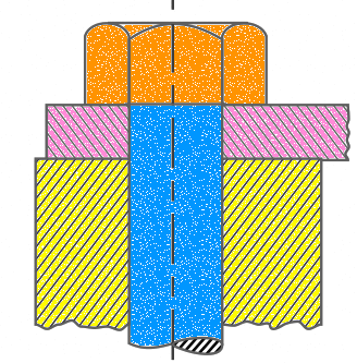
On the other hand, if the bolt is very yielding as compared with the connected members, as shown in the above figure, then the resultant load will be either the initial tension or the external load, whichever is greater.
The actual conditions usually lie between the two extremes. In order to determine the resultant axial load (P) on the bolt, the following equation may be used.

where
P1 = Initial tension due to tightening of the bolt
P2 = External load on the bolt
a = Ratio of elasticity of connected parts to the elasticity of bolt
For soft gaskets and large bolts, the value of a is high and the value of a/(1 + a) is approximately equal to unity so that the resultant load is equal to the sum of the initial tension and the external load.
For hard gaskets or metal-to-metal contact surfaces and with small bolts, the value of a is small and the resultant load is mainly due to the initial tension (or external load, in rare cases it is greater than initial tension).
The value of ‘a’ may be estimated by the designer to obtain an approximate value for the resultant load. The values of a/(1 + a) (i.e. K) for various types of joints are shown below the table.
| Type of joint | K = a(1+a) (in mm) |
| Metal to metal joint with through bolts | 0.00 to 0.10 |
| Hard copper gasket with long through bolts | 0.25 to 0.50 |
| Soft copper gasket with long through bolts | 0.50 to 0.75 |
| Soft packing with through bolts | 0.75 to 1.00 |
| Soft packing with studs | 1.00 |
The designer thus has control over the influence on the resultant load on a bolt by proportioning the sizes of the connected parts and bolts and by specifying the initial tension in the bolt.
Conclusion
These are the different types of stresses that may be induced for a bolted joint, which may result in unpredictable failures of the joints. in order to prevent failures, a large safety margin has to be maintained. The above-mentioned formulas and relations for the initial stress, and the stress due to external factors can help you calculate the selected bolt is safe or not. Let us know if this article helps your requirement.

Leave a Reply