In the previous article, we have discussed the Otto cycle, The Otto cycle is an idealized cycle for the spark-ignition engine whereas the Diesel cycle is the idealized cycle for the Compression Ignition Engines. In the Ideal cycle, the heat addition process needs no special device such as the ignition system. Let’s discuss the diesel Cycle in more detail.
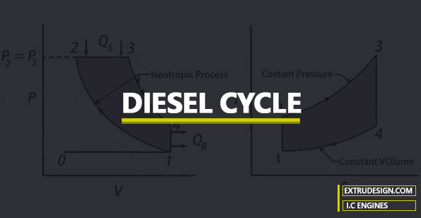
Diesel Cycle
The Diesel cycle is also similar to the Otto Cycle except the heat addition process is a constant pressure process in Diesel cycle whereas in Otto cycle it is a Constant volume process according to the P-V diagram and the T-S diagram.
In other words, the combustion takes place in the cylinder without any need for the ignition system. such engines are called compress Ignition Engines.
In actual Spark-Ignition Engines, the upper limit of the compression ratio is limited by the self-Ignition temperature of the fuel.
In the Compression Ignition engines, the air in the cylinder is compressed due to mechanical compression and the fuel is injected into the cylinder which contains highly compressed air at high temperature than the self-Ignition temperature of the injected fuel to ignite the fuel.
Which means in the Diesel cycle, the heat addition process takes place while constant pressure. So because of this, the Diesel cycle also said as the Constant Pressure cycle as well.
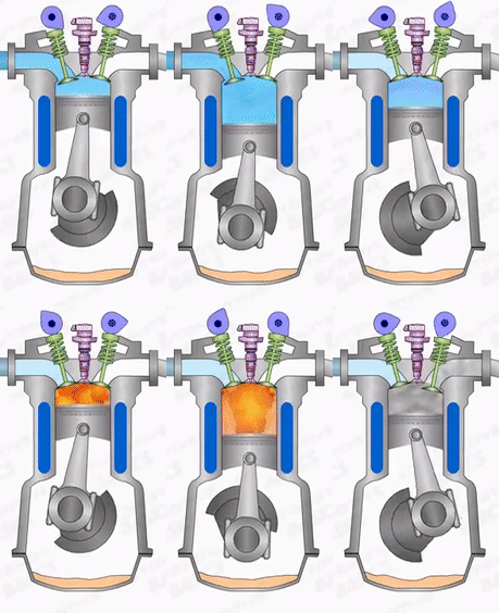
The four thermodynamic operations in the compression Ignition Engines are
- Suction or intake stroke,
- Compression stroke,
- Expansion or power stroke,
- Exhaust stroke.
All these four processes are explained with the help of a P-V diagram and T-S diagram in the Diesel Cycle. which is as similar to the Otto cycle except for the 2 → 3 heat addition constant pressure process.
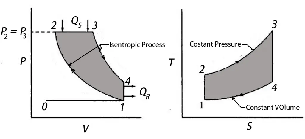
P-V diagram and T-S diagram in the Diesel Cycle
0 → 1 and 1 → 0
When the engine is working on the full throttle, the Process 0 → 1 and 1 → 0 represents the suction and the exhaust process of Thermodynamic cycle in the P-V diagram and the effect of these two processes considered as nullified.
1 → 2
The process 1 → 2 is the isotropic compression of the air in the cylinder while piston moves from the bottom dead centre (BDC) to the top dead centre (TDC)
2 → 3
During the process, 2 → 3 the heat is supplied at a constant pressure. This is the compression ignition and the combustion of the injected fuel is takes place in the cylinder during this process 2 → 3.
3 → 4 & 4 → 1
These two processes 3 → 4 & 4 → 1 will represent the isotropic expansion (Piston moves from the Top dead centre to the bottom dead centre) and the constant volume heat rejection respectively.
Thermodynamically, the efficiency of the Diesel Cycle is given by

Work done by the system = Heat supplied (QS)- Heat rejected (QR)
W = QS – QR
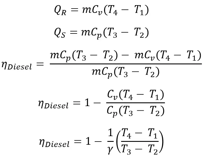
Note: r is the compression Ratio whereas the rc is the cut off ratio
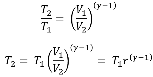
Considering the isotropic processes 1 → 2
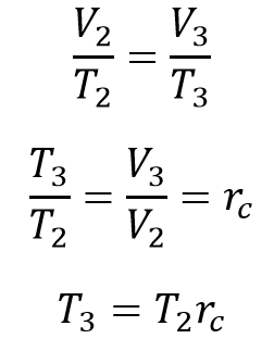
Considering the constant pressure process 2 → 3
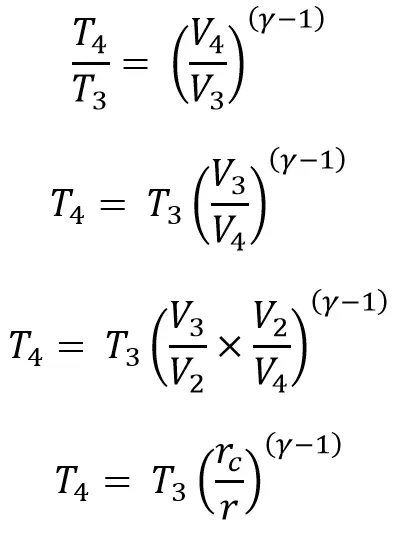
Considering the 3 → 4 process
Now we can write the efficiency of the Diesel Cycle is from all the above equations
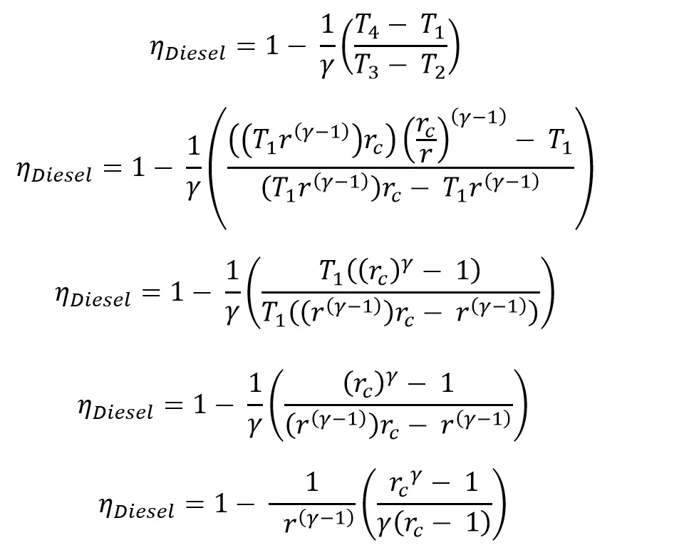
The efficiency of the Diesel Engine is different from the Otto cycle. For the given compression ratio the Otto cycle has more efficiency. From the above Diesel cycle efficiency equation. the
For the diesel engine usually, we have to maintain the higher compression ratios to get the high efficiency compared to the Otto cycle engine (Spar Ignition Engine).
The compression ratios of the Diesel engines usually ranging from 16 to 20 whereas the Otto cycle engine is
So due to maintaining the higher compression ratios, the efficiency of the diesel engine is higher than the engines running based on the Otto cycle.
Conclusion
We have discussed the combustion process of the Diesel cycle engine with the P-V and T-S diagrams and also we have derived the equation for the Efficiency and we compared the efficiency of the Diesel cycle along with the Otto cycle. If you have any thoughts about this topic, Please let us know in the comment section below.

Leave a Reply