We have already discussed what a flywheel is and its uses in the previous article. A flywheel used in machines serves as a reservoir that stores energy during the period when the supply of energy is more than the requirement and releases it during the period when the requirement of energy is more than the supply. Let us discuss the Construction of Different Flywheels.

Flywheel
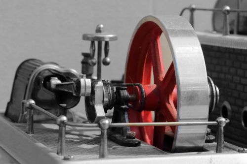
As we have said the flywheel used in machines serves as a reservoir that stores energy. In the case of steam engines, internal combustion engines, reciprocating compressors, and pumps, the energy is developed during one stroke and the engine is to run for the whole cycle on the energy produced during this one stroke.
For example, in I.C. engines, the energy is developed only during power stroke which is much more than the engine load, and no energy is being developed during suction, compression, and exhaust strokes in the case of four-stroke engines and during compression in the case of two-stroke engines. The excess energy developed during a power stroke is absorbed by the flywheel and released it to the crankshaft during other strokes in which no energy is developed, thus rotating the crankshaft at a uniform speed. A little consideration will show that when the flywheel absorbs energy, its speed increases, and when it releases, the speed decreases. Hence a Flywheel does not maintain a constant speed, it simply reduces the fluctuation of speed.

In machines where the operation is intermittent like punching machines, shearing machines, riveting machines, crushers, etc., the flywheel stores energy from the power source during the greater portion of the operating cycle and gives it up during a small period of the cycle. Thus the energy from the power source to the machines is supplied practically at a constant rate throughout the operation.
The function of a governor in the engine is entirely different from that of a flywheel. It regulates the mean speed of an engine when there are variations in the load, e.g. when the load on the engine increases, it becomes necessary to increase the supply of working fluid. On the other hand, when the load decreases, less working fluid is required. The governor automatically controls the supply of working fluid to the engine with the varying load conditions and keeps the mean speed within certain limits.
As discussed above, the flywheel does not maintain a constant speed, it simply reduces the fluctuation of speed. In other words, a flywheel controls the speed variations caused by the fluctuation of the engine turning moment during each cycle of operation. It does not control the speed variations caused by the varying load.
Construction of Flywheels
We have discussed the different stresses in Flywheel arms and Flywheel Rim. We also discussed the Design of the Flywheel. So it will be easier for us to proceed with discussing the Construction of Flywheels if we have read all of these.
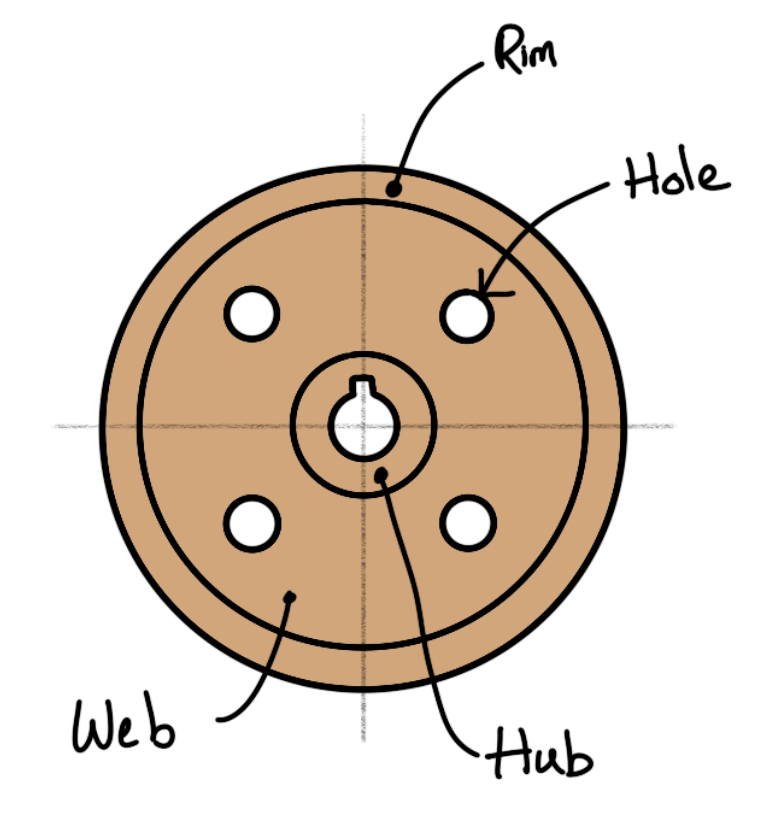
The flywheels of smaller size (up to 600 mm diameter) are casted in one piece. The rim and hub are joined together by means of a web as shown in the following figure. The holes in the web may be made for handling purposes.

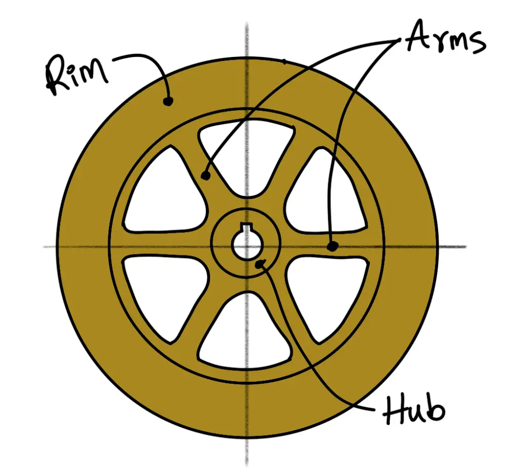
In case the flywheel is of larger size (up to 2.5 metre diameter), the arms are made instead of the web, as shown in the following figure. The number of arms depends upon the size of the flywheel and its speed of rotation.

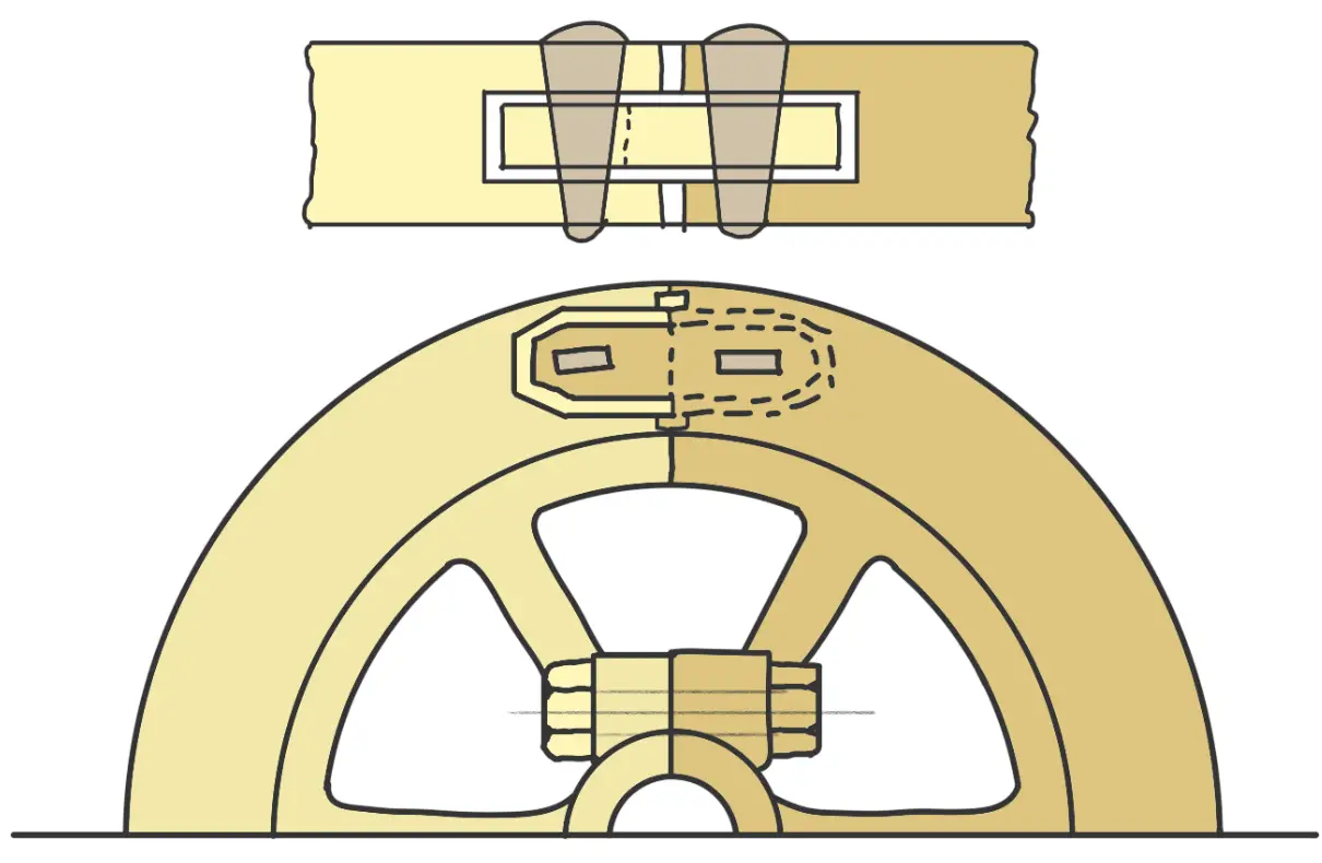
But the flywheels above 2.5 metres in diameter are usually casted in two piece. Such a flywheel is known as Split Flywheel. A split flywheel has the advantage of relieving the shrinkage stresses in the arms due to unequal rate of cooling of casting. A flywheel made in two halves should be split at the arms rather than between the arms, in order to obtain better strength of the joint. The two halves of the flywheel are connected by means of bolts through the hub, as shown in the following figure.

The two halves are also joined at the rim by means of a cotter joint as shown in the above figure.
The two halves are also joined at the rim by means of shrink links as shown in the following figure.

The width or depth of the shrink link is taken as 1.25 to 1.35 times the thickness of the link. The slot in the rim into which the link is inserted is made slightly larger than the size of the link.
The relative strength of a rim joint and the solid rim are given in the following table.
| S.No. | Type of construction | Relative strength |
| 1 | Solid rim. | 1.00 |
| 2 | Flanged joint, bolted, rim parted between arms. | 0.25 |
| 3 | Flanged joint, bolted, rim parted on an arm. | 0.50 |
| 4 | Shrink link joint. | 0.60 |
| 5 | Cotter or anchor joints. | 0.70 |
This is all about the Construction of Flywheels. Let us know what you think of this article in the comment section below.

Leave a Reply