Among the basic components of an Internal Combustion engine, the Connecting Rod for IC Engine is the most critical. The connecting rod is subjected to alternating direct compressive and tensile forces. Since the compressive forces are much higher than the tensile forces, therefore the cross-section of the connecting rod is designed as a strut and Rankine’s formula is used. In the previous article, we discussed the design of Connecting Rod, and in this article, we will discuss the Forces Acting on a Connecting Rod.

A connecting rod subjected to an axial load W may buckle with the X-axis as the neutral axis (i.e. in the plane of motion of the connecting rod) or the Y-axis as the neutral axis (i.e. in the plane perpendicular to the plane of motion).
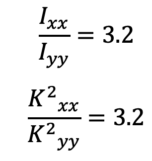
The connecting rod is considered like both ends hinged for buckling about X-axis and both ends fixed for buckling about Y-axis. A connecting rod should be equally strong in buckling about either axes.
Forces Acting on a Connecting Rod
The connecting rod is subjected to the following forces:
- Force due to gas or steam pressure and inertia of reciprocating parts,
- Inertia bending forces.
We shall now derive the expressions for the Forces Acting on a Connecting Rod of a horizontal engine, as discussed below:
Force due to gas or steam pressure and inertia of reciprocating parts
Consider a connecting rod PC as shown in the following schematic diagram.
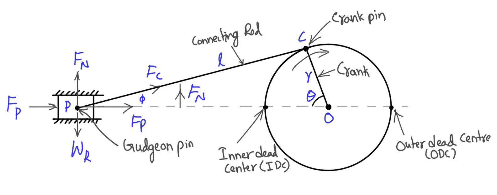
Let
p = Pressure of gas or steam,
A = Area of the piston,
mR = Mass of reciprocating parts = Mass of piston, gudgeon pin etc. + ⅓ rd mass of connecting rod,
ω = Angular speed of crank,
φ = Angle of inclination of the connecting rod with the line of stroke
θ = Angle of inclination of the crank from the inner dead center,
r = Radius of crank,
l = Length of connecting rod, and
n = Ratio of length of connecting rod to radius of crank = l / r.
We know that the force on the piston due to the pressure of gas or steam,
FL = Pressure × Area = p × A
and inertia force of reciprocating parts,
FI = Mass × Acceleration
We know the Acceleration of reciprocating parts

The force on the piston due to the pressure of gas or steam can be written as

It may be noted that in a horizontal engine, reciprocating parts are accelerated from rest during the first half of the stroke (i.e. when the piston moves from the inner dead center to the outer dead center). It is then retracted during the latter half of the stroke (i.e. when the piston moves from the outer dead center to the inner dead center).
The inertia force due to the acceleration of reciprocating parts, opposes the force on the piston. On the other hand, the inertia force due to retardation of the reciprocating parts, helps the force on the piston.
The net force acting on the piston pin (or gudgeon or wrist pin),
FP = Force due to pressure of gas or steam ± Inertia force
FP = FL ± FI
The –ve sign is used when the piston is accelerated and the +ve sign is used when the piston is retracted.
The force FP gives rise to a force FC in the connecting rod and a thrust FN on the sides of the cylinder walls (or a normal reaction on crosshead guides). From the above schematic diagram, we see that force in the connecting rod at any instant.
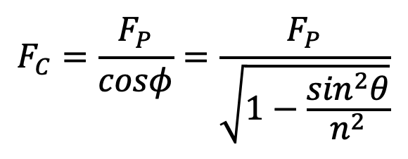
The force in the connecting rod will be maximum when the crank and the connecting rod are perpendicular to each other (i.e. when θ = 90°). But at this position, the gas pressure would be decreased considerably. Thus, for all practical purposes, the force in the connecting rod (FC) is taken equal to the maximum force on the piston due to the pressure of gas or steam (FL), neglecting piston inertia effects.
Inertia Bending Forces
Consider a connecting rod PC and a crank OC rotating with uniform angular velocity ω rad /s. In order to find the acceleration of various points on the connecting rod, draw Klien’s acceleration diagram CQNO as shown in the following figure.
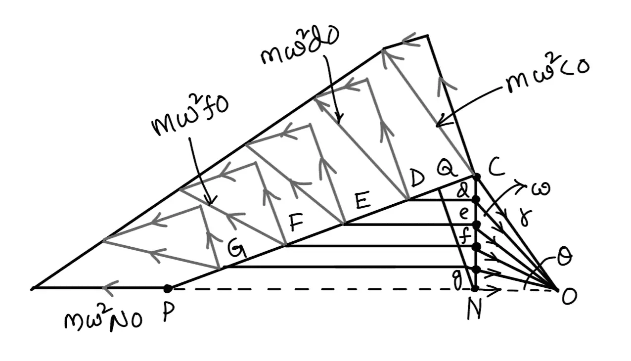
CO represents the acceleration of C towards O and NO represents the acceleration of P towards O. The acceleration of other points such as D, E, F, and G, etc. on the connecting rod PC may be found by drawing horizontal lines from these points to intersect CN at d, e, f, and g respectively. Now dO, eO, fO and gO represents the acceleration of D, E, F, and G all towards O. The inertia force acting on each point will be as follows :
Inertia force at C = m × ω2 × CO
Inertia force at D = m × ω2 × dO
Inertia force at E = m × ω2 × eO
…. so on.
The inertia forces will be opposite to the direction of acceleration or centrifugal forces. The inertia forces can be resolved into two components, one parallel to the connecting rod and the other perpendicular to the rod. The parallel (or longitudinal) components add up algebraically to the force acting on the connecting rod (FC) and produce thrust on the pins. The perpendicular (or transverse) components produce bending action (also called whipping action) and the stress induced in the connecting rod is called whipping stress.
A little consideration will show that the perpendicular components will be maximum when the crank and connecting rod are at right angles to each other.
The variation of the inertia force on the connecting rod is linear and is like a simply supported beam of variable loading as shown in the following figures.
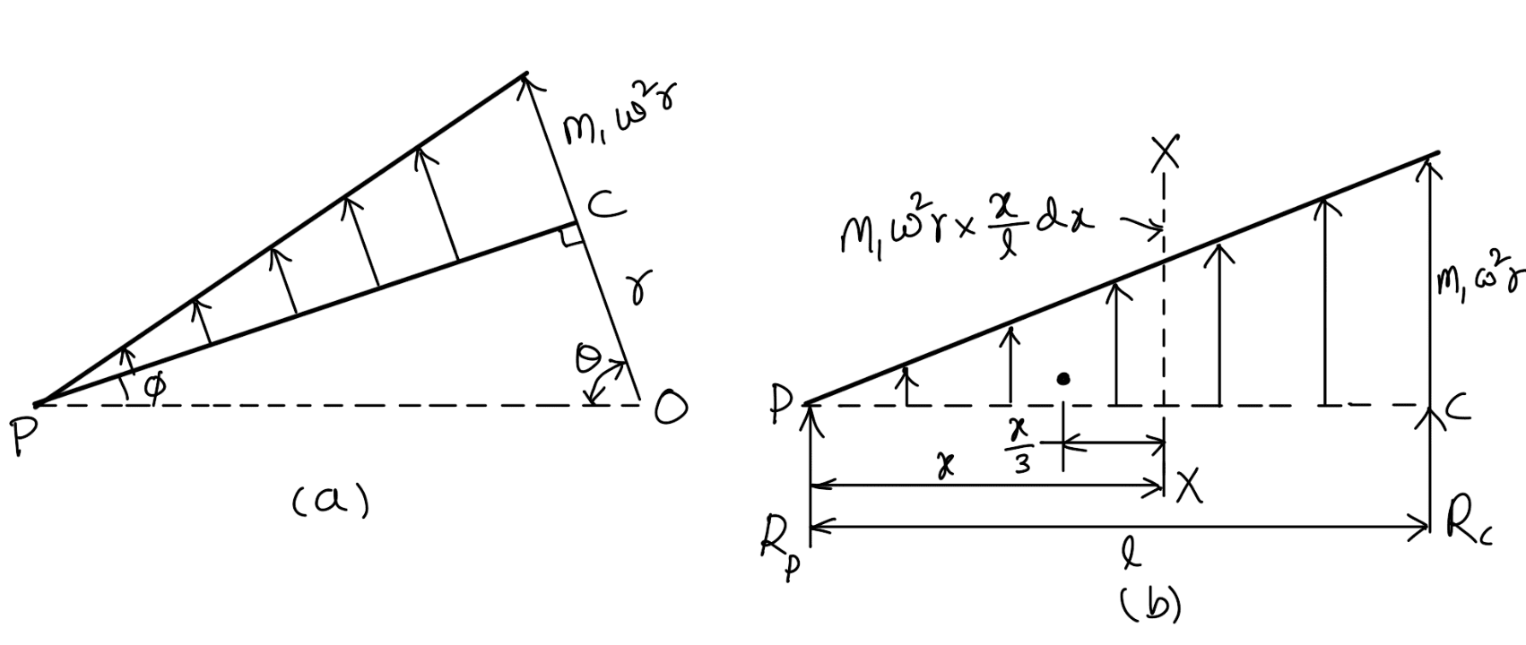
Assuming that the connecting rod is of uniform cross-section and has mass m1 kg per unit length, therefore
Inertia force per unit length at the crank pin = m1 × ω2r
and inertia force per unit length at the gudgeon pin = 0
Inertia forces due to a small element of length dx at a distance x from the gudgeon pin P,
dFI = m1 × ω2r × (x÷l) × dx
Resultant inertia force,
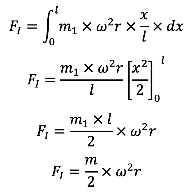
This resultant inertia force acts at a distance of 2l / 3 from the gudgeon pin P.
Since it has been assumed that ⅓ rd mass of the connecting rod is concentrated at gudgeon pin P (i.e. small end of connecting rod) and ⅔ rd at the crank pin (i.e. big end of connecting rod), therefore the reactions at these two ends will be in the same proportion, i.e.
RP = ⅓ F1
RC = ⅔ F1
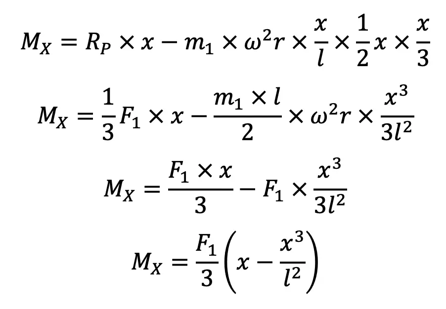
Now the bending moment acting on the rod at section X-X at a distance x from P,
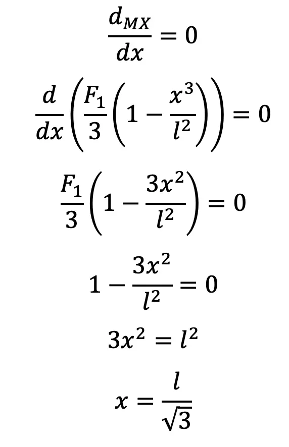
For the maximum bending moment, differentiate MX with respect to x and equate to zero, i.e.
Substituting this value of x in the above bending moment equation we have a maximum bending moment,
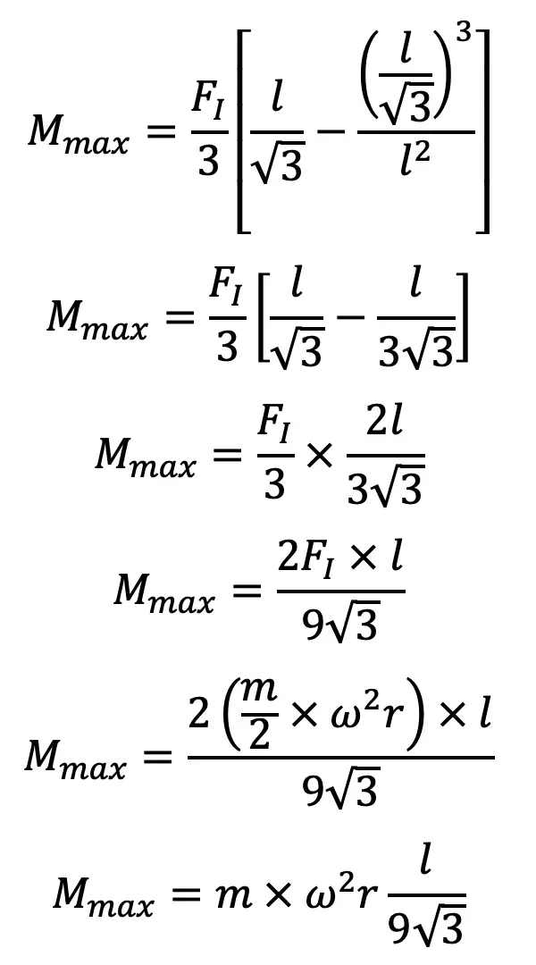
and the maximum bending stress, due to the inertia of the connecting rod,
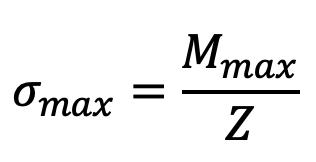
where Z = Section modulus.
From above we see that the maximum bending moment varies as the square of the speed, therefore, the bending stress due to high speed will be dangerous. It may be noted that the maximum axial force and the maximum bending stress do not occur simultaneously.
In an I.C. engine, the maximum gas load occurs close to the top dead center whereas the maximum bending stress occurs when the crank angle θ = 65° to 70° from the top dead center. The pressure of the gas falls suddenly as the piston moves from the dead center.
In steam engines, even though the pressure is maintained till cut off occurs, the speed is low and therefore the bending stress due to inertia is small. Thus the general practice is to design a connecting rod by assuming the force in the connecting rod (FC) is equal to the maximum force on the piston due to the pressure of gas or steam (FL), neglecting piston inertia effects and then checking for bending stress due to inertia force (i.e. whipping stress).
Example problem to design a Connection Rod I-section
Problem Statement: Determine the dimensions of an I-section connecting rod for a petrol engine from the following data and the relations from the different Forces Acting on a Connecting Rod:
Diameter of the piston = 110 mm
Mass of the reciprocating parts = 2 kg
Length of the connecting rod from center to center = 325 mm
Stroke length = 150mm
Speed in R.P.M. = 1500 with a possible Overspeed of 2500
Compression ratio = 4: 1
Maximum explosion pressure = 2.5 N/mm2
Answer:
We know that the radius of the crank, r = Stroke length /2 150 / 2 = 75mm = 0.075m
The ratio of the length of connecting rod to the radius of the crank n = l/r = 325/75 = 4.3
We know that the maximum force on the piston due to pressure,
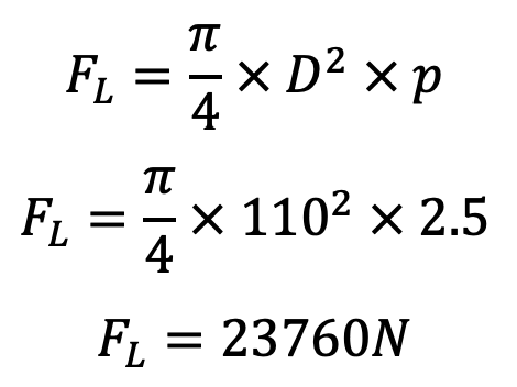
The maximum angular speed,
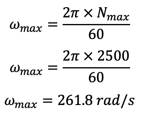
We know that the maximum inertia force of reciprocating parts,

The inertia force of reciprocating parts is maximum when the crank is at the inner dead center, i.e. when θ = 0°
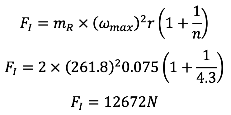
Since the connecting rod is designed by taking the force in the connecting rod (FC) equal to the maximum force on the piston due to gas pressure (FL), therefore
Force in the connecting rod, FC = FL = 23760N
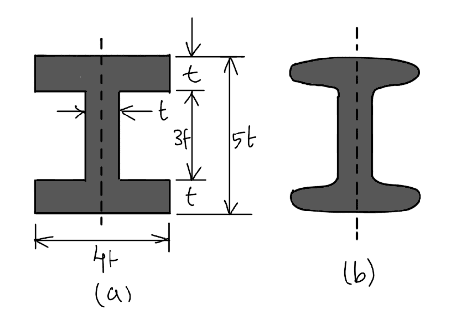
Consider the I-section of the connecting rod with the proportions as shown in the following figure. We have discussed this in the previous article that for such a section
We have also discussed that the connecting rod is designed for buckling about the X-axis (i.e. in a plane of motion of the connecting rod), assuming both ends are hinged. Taking a factor of safety as 6, the buckling load,
Wcr = FC × 6 = 23760 × 6 = 142560N
and area of cross-section, A = 2 (4t × t) + t × 3t = 11 t2 mm2
Moment of inertia about the X-axis,

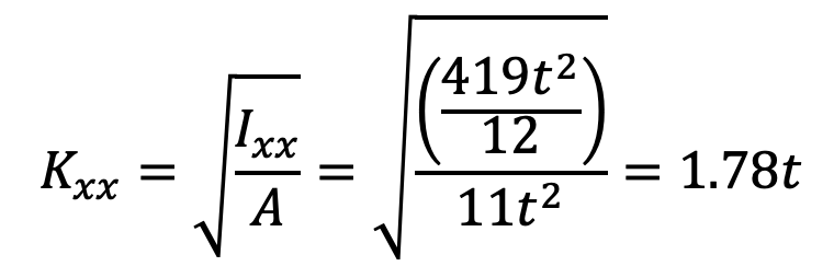
The radius of gyration,
We know that the equivalent length of the rod for both ends is hinged, L = l = 325mm
Taking for mild steel, σc = 320 MPa = 320 N/mm2 and a = 1 / 7500, we have from Rankine’s formula,
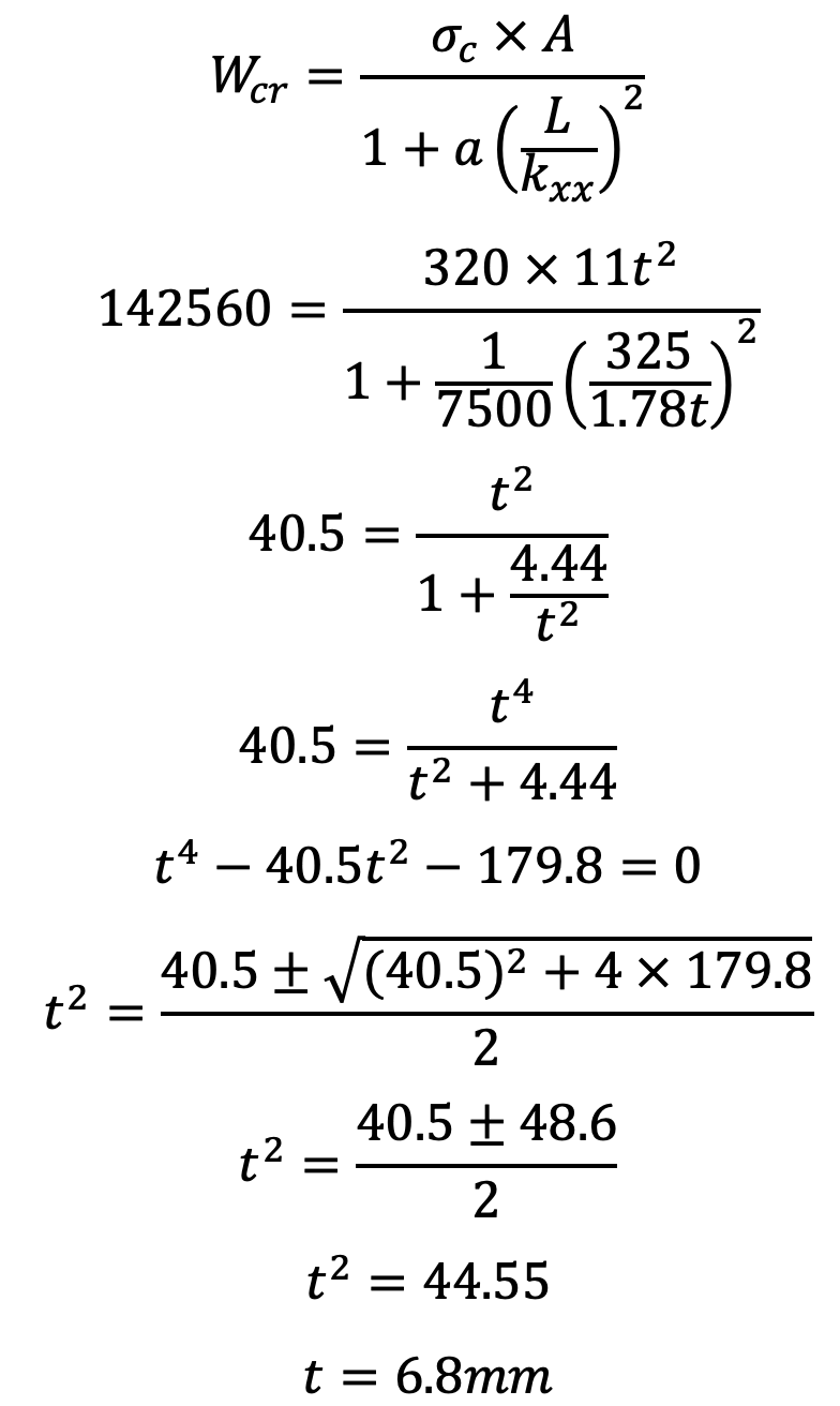
Therefore, the dimensions of the cross-section of the connecting rod are
Height = 5t = 5 × 6.8 = 34mm
Width = 4t = 4 × 6.8 = 27.2mm
The thickness of flange and web = t = 6.8mm = 0.0068m
Now let us find the bending stress due to the inertia force on the connecting rod.
We know that the mass of the connecting rod per meter length,
m1 = Volume × density
m1 = Area × length × density
m1 = A × l × ρ
m1 = 11t2 × l × ρ
m1 = 11(0.0068)2 1 × 7800 = 3.97 kg
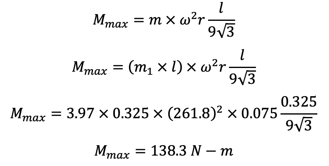
Maximum bending moment,
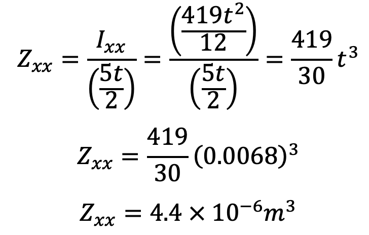
Section modulus,
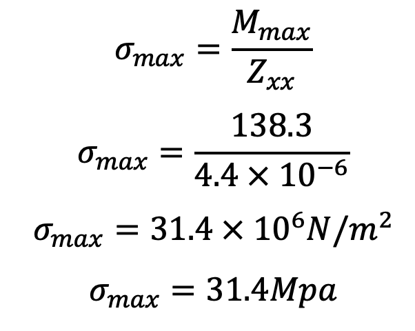
The maximum bending or whipping stress due to inertia bending forces,
The maximum compressive stress in the connecting rod will be,
σc(max) = Direct compressive stress + Maximum bending stress
σc(max) = (320/6) + 31.4
σc(max) = 84.7 Mpa
Would you like to solve an exercise problem?
Exercise Problem Statement: Determine the dimensions of an I-section connecting rod for an internal combustion engine having the following specifications:
Diameter of the piston = 120mm
Mass of reciprocating parts = 350 kg/m2 of piston area
Length of connecting rod = 350mm
Engine revolutions per minute = 1800rpm
Maximum explosion pressure = 3 N/mm2
Stroke length = 180mm.
The flange width and the depth of the I-section rod are in the ratio of 4 t : 6 t where t is the thickness of the flange and web. Assume yield stress in compression for the material as 330 MPa and a factor of safety as 6.
Solve this and let us know the answer in the comment section below. I will help you with the correct answer. And what do you think about this detailed article on Forces Acting on a Connecting Rod? Let us know your thoughts in the comment section below.

Good