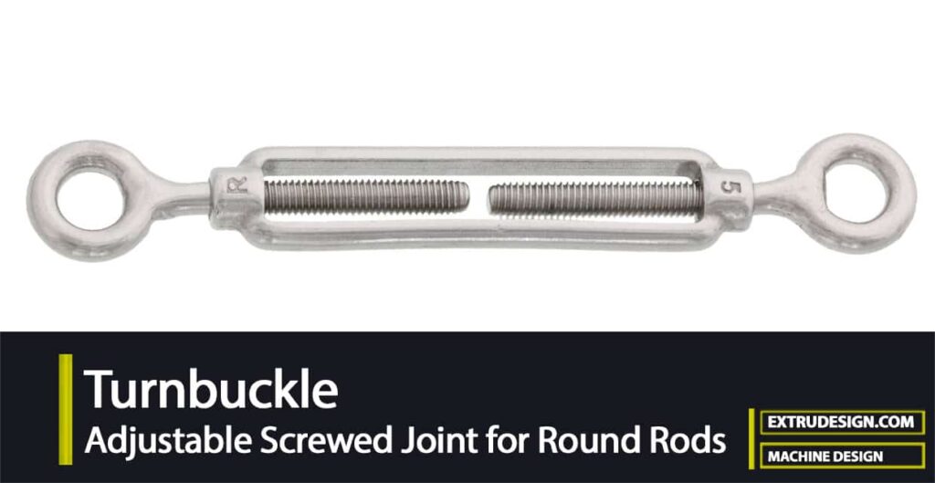
A turnbuckle is a joint or also known as a coupling to join two threaded rods together. This turnbuckle is also referred to as Rigging screws or an Adjustable Screwed Joint for Round Rods. Let us see how we can design Turnbuckle to connect two threaded rods.

Turnbuckle
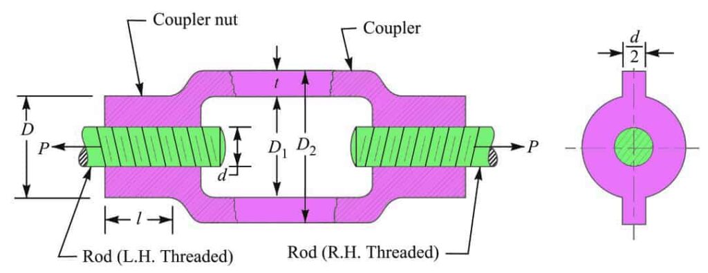
In this adjustable screwed joint, one of the rods should have a right-hand thread and the other rod should have left-hand threads. The rods are screwed to a couple that has a threaded hole. This couple can be a closed body or an open body.
The open body turnbuckle is as shown in the above figure. Whereas the closed turnbuckle is explained below. In this article, we will design a closed body adjustable screwed joint.
The closed body turnbuckle has a different design such as a hexagonal or rectangular shape in the center and around at both ends in order to facilitate the rods to tighten or loosen with the help of a spanner when required.
Instead of a spanner, a round iron rod may be used to tighten the turnbuckle. The iron rod is inserted in a hole in the coupler as shown dotted in below schematic diagram of a turnbuckle with a hexagonal shape.

A turnbuckle is commonly used in engineering practice such as in airplanes, as a rigging screw for tensioning cable and ropes. The above-shown turnbuckle is made hollow in the middle to reduce its weight.
In this case, the two ends of the rods may also be seen. It is not necessary that the material of the rods and the turnbuckle may be the same or different. It depends upon the pull acting on the joint
Design of Turnbuckle / Rigging Screw / Adjustable Screwed Joint
As we mentioned above this is a Turnbuckle also known as Rigging Screw or an Adjustable Screwed Joint. In order to design it, we need to assume the turnbuckle is subjected to an axial load P, as shown below schematic.

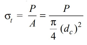
Due to this load, the threaded rod will be subjected to tensile stress whose magnitude is given by

where dc = Core diameter of the threaded rod
In order to drive the rods, the torque required is given by
T = P tan(α+φ)(dp/2)
where α = Helix angle,
tan φ = Coefficient of friction between the threaded rod and the coupler nut
dp= Pitch diameter or mean diameter of the threaded rod
The Shear stress produced by the torque,

The usual values of tan α, tan φ and dp are as follows : tan α = 0.03, tan φ = 0.2, and dp = 1.08 dc
Substituting these values in the above expression, we get

Since the threaded rod is subjected to tensile stress as well as shear stress, therefore maximum principal stress,

Given a margin for the higher coefficient of friction, the maximum principal stress may be taken as 1.3 times the normal stress.
Therefore for designing a threaded section, we shall take the design load as 1.3 times the normal load.
Therefore the Design load, (Pd) = 1.3 P
The following procedure may be adopted in designing a turnbuckle :
1. Diameter of the rods
The diameter of the rods (d) may be obtained by considering the tearing of the threads of the rods at their roots.
We know that the Tearing resistance of the threads of the rod

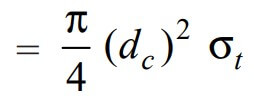
Let us equate the design load (Pd) to the tearing resistance of the threads, we can write

where
dc = Core diameter of the threads of the rod, and
σt = Permissible tensile stress for the material of the rod.
From the above expression, the core diameter of the threads can be determined.
The nominal diameter of the threads or diameter of the rod can be taken from the Table given here corresponding to the core diameter, assuming coarse threads.
2. Length of the coupler nut
The length of the coupler nut (l) is obtained by considering the shearing of the threads at their roots in the coupler nut.
We know that the Shearing resistance of the threads of the coupler nut
= (π dc × l) τ
where τ = Shear stress for the material of the coupler nut.
Equating the design load to the shearing resistance of the threads in the coupler nut, we have
Pd = (π dc × l ) τ
From this expression, the value of l may be calculated.
In actual practice, the length of coupler nut (l) is taken d to 1.25 d for steel nuts and 1.5 d to 2 d for cast iron and softer material nut.
The length of the coupler nut may also be checked for crushing of threads. We know that the Crushing resistance of the threads in the coupler nut

where
σc = Crushing stress induced in the coupler nut
n = Number of threads per mm length.
Equating the design load to the crushing resistance of the threads, we have

From this expression, the induced crushing stress (σc) can be determined.
3. Outside diameter of the coupler nut
The outside diameter of the coupler nut (D) may be obtained by considering the tearing at the coupler nut.
We know that Tearing resistance at the coupler nut

where
σt = Permissible tensile stress for the material of the coupler nut.
Equating the axial load to the tearing resistance at the coupler nut, we can write

From this expression, the value of D may be calculated.
In actual practice, the diameter of the coupler nut (D) is taken from 1.25 d to 1.5 d
4. Outside diameter of the coupler
The outside diameter of the coupler (D2) may be obtained by considering the tearing of the coupler.
We know the Tearing resistance of the coupler is given by

where D1 = Inside diameter of the coupler. It is generally taken as (d + 6 mm)
σt = Permissible tensile stress for the material of the coupler.
Equating the axial load to the tearing resistance of the coupler, we have

From this expression, the value of D2 may be calculated. In actual practice, the outside diameter of the coupler (D2) is taken as 1.5 d to 1.7 d.
If the section of the coupler is to be made hexagonal or rectangular to fit the spanner, it may be circumscribed over the circle of outside diameter D2.
5. The length of the coupler between the nuts (L) depends upon the amount of adjustment required. It is usually taken as 6 d.
6. The thickness of the coupler is usually taken as t = 0.75 d and thickness of the coupler nut (t1) = 0.5 d.
These are all the parameters of a Turnbuckle that we can use to design a turnbuckle.
Let us solve a sample problem to design a Turnbuckle or Rigging screw or an adjustable screwed joint to pull in the tie-rod of an iron roof truss.
Example Problem Statement
The pull in the tie-rod of an iron roof truss is 50 kN. Design a suitable adjustable screwed joint. The permissible stresses are 75 MPa in tension, 37.5 MPa in shear, and 90 MPa in crushing
Answer:
Given data
Pull Load (P) = 50 kN = 50 × 103 N
Permissible Tensile Stress (σt) = 75 MPa = 75 N/mm2
Permissible Shear Stress (τ) = 37.5 MPa = 37.5 N/mm2
We know that the design load for the threaded section,
Pd = 1.3 P = 1.3 × 50 × 103 = 65 × 103 N
An adjustable screwed joint, as shown all the way above, is suitable for the given purpose. The various dimensions for the adjustable screwed joint can be determined as discussed above. Let us determine these parameters.
1. Diameter of the tie rod
Let us say
d = Diameter of the tie rod, and
dc = Core diameter of threads on the tie rod.
Considering tearing of the threads on the tie rod at their roots. We know that design load (Pd),

65×103 = π/4 (dc)2 × 75
65×103 = 59 (dc)2
(dc)2 = 65 × 103 / 59
(dc)2 = 1100
dc = 33.2mm
From the Table given here, for coarse series, we find that the standard core diameter is 34.093 mm and the corresponding nominal diameter of the threads or diameter of the tie rod, d = 39 mm Ans
2. Length of the coupler nut
Let us say l = Length of the coupler nut.
Considering the shearing of threads at their roots in the coupler nut. We know that design load (Pd),
P = (π dc.l ) τ
65 × 103 = (π dc.l ) τ
65 × 103 = π × 34.093 × l × 37.5
65 × 103 = 4107 l
l = 65 × 103 / 4017
l = 16.2 mm
Since the length of the coupler nut is taken from d to 1.25 d, therefore we shall take
l = d = 39 mm.
We shall now check the length of the coupler nut for crushing of threads.
From the Table given here, for coarse series, we find that the pitch of the threads is 4 mm.
Therefore the number of threads per mm length,
n = 1 / 4 = 0.25
We know that design load (Pd),

65 × 103 = π/4 [(39)2 – (34.093)2] × 0.25 × 39 × σc
σc = 65 × 103 / 2750
σc = 23.6 N/mm2 = 23.6MPa
Since the induced crushing stress in the threads of the coupler nut is less than the permissible stress, therefore the design is satisfactory
3. Outside diameter of the coupler nut
Let us say D = Outside diameter of the coupler nut
Considering tearing of the coupler nut. We know that axial load (P)

50 × 103 = π/4 (D2 – (39)2)
D2 – (39)2 = 50 × 103 / 59
D2 – (39)2 = 848
D2 = 848 + (39)2
D2 = 2369
D = 48.7
Let us take the Outside diameter of the coupler nut value as 50mm.
Since the minimum outside diameter of the coupler nut is taken as 1.25 d = 1.25 × 39 = 48.75 m
Therefore the above value of D is satisfactory.
4. Outside diameter of the coupler
Let D2 = Outside diameter of the coupler, and
D1 = Inside diameter of the coupler = d + 6 mm = 39 + 6 = 45mm
Considering tearing of the coupler. We know that axial load (P),

50 × 103 = π/4 [(D2)2– (45)2]× 75
50 × 103 = [(D2)2 – (45)2 ] × 59
(D2)2 = 50 × 103 / 59 + (45)2
(D2)2 = 2873
D2 = 53.6 mm
Since the minimum outside diameter of the coupler is taken as 1.5 d = 1.5 × 39 = 58.5 say 60mm
Therefore we shall take D2 = 60 mm
5. Length of the coupler between nuts (L) = 6 d = 6 × 39 = 234mm
6. Thickness of the coupler (t1) = 0.75 d = 0.75 × 39 = 29.25 let us take 30mm
7. The thickness of the coupler nut (t) = 0.5 d = 0.5 × 39 = 19.5 let us take 20mm.
This is how you can calculate all the parameters of the turnbuckle to design or choose the right size of a turnbuckle for pulling in the tie-rod of an iron roof truss.

Leave a Reply