In the previous article, we have discussed the different Optical Measurement Techniques, the first one is the Tool Maker’s Microscope, the second one is the Profile Projector, the third one is this optical square. In this article, we are going to discuss briefly Optical Square in metrology.

Optical Square
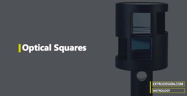
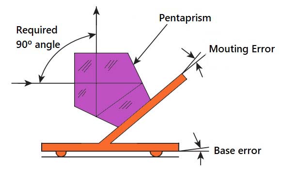
An optical square is useful in turning the line of sight by 90° from its original path. Many optical instruments, especially microscopes, have this requirement. An Optical square is are essentially a pentagonal prism (pentaprism). Regardless of the angle at which the incident beam strikes the face of the prism, it is turned through 90° by internal reflection. Unlike a flat mirror, the accuracy of a pentaprism will not be affected by the errors present in the mounting arrangement.

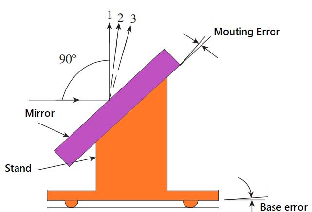
1 — Reflected ray without errors
2 — Reflected ray due to mounting error
3 — Reflected ray due to base error
From the above schematic diagram, a mirror is kept at an angle of 45° with respect to the incident ray of light so that the reflected ray will be at an angle of 90° with respect to the incident ray. It is observed that any error in the mounting of the mirror or in maintaining its base parallel, in a fixed reference, to the beam is greatly magnified by the optical lever effect. These two errors in combination may even be greater than the workpiece squareness error.

This problem may be overcome by using an optical square. The above schematic diagram illustrates the optical path through an optical square. The incident ray is reflected internally from two faces and emerges from the square at exactly 90° to the incident light. This is a remarkable property. Any slight deviation or misalignment of the prism does not affect the right angle movement of the light ray.
Optical squares are of two types. One type is fitted into instruments like telescopes, wherein an optical square is factory-fitted to ensure that the line of sight is perpendicular to the vertex. The second type comes with the necessary attachments for making adjustments to the line of sight. This flexibility allows optical squares to be used in a number of applications in metrology.

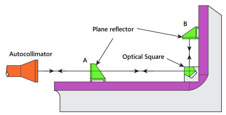
The above schematic diagram illustrates the use of optical squares to test the squareness of machine slideways. The squareness of the vertical slideway with respect to a horizontal slideway or bed is of utmost importance in machine tools. The test setup requires an autocollimator, plane reflectors, and an optical square. It is necessary to take only two readings, one with the reflector at position A and a second at position B, the optical square being set down at the intersection of the two surfaces when the reading at B is taken. The difference between the two readings is the squareness error.
Conclusion
In this article, we have discussed one of the optical measuring techniques Optical squares with detailed construction and working principles, and how to use it. Let us know your thoughts in the comment section below.

Leave a Reply