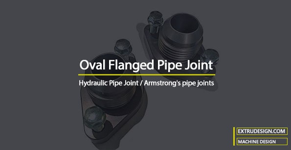
The Oval flanged Pipe Joints are mostly used in small pipes with diameters up to 175mm. This Oval Flanged Pipe Joint is mostly used in Hydraulic applications. In the previous article, we have discussed the Circular Flanged Pipe joint. To design an Oval Flanged Pipe Joint we need to determine the main parameters such as flange thickness, PCD, and bolt diameters based on the fluid pressure inside the pipe. In this article, we will discuss how to design an Oval flanged pipe joint for a given pipe with specified fluid pressure.

Oval Flanged Pipe Joint
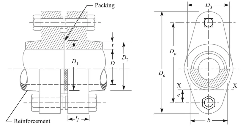
In most cases, Oval flanged pipe joints are integral parts of the pipe, in some cases, they are screwed to the pipe ends. As you can see the spigot and socket are provided to locate the pipe bore in a straight line.

As we have mentioned in the previous article that, it is assumed that the fluid pressure is acting between the two flanges and trying to make them apart with a pressure existing at the leaking point. In order to keep the flanges together, the bolted joint needs to withstand the tensile stress.
∴ Let us calculate the Force trying to separate the two flanges apart,
F1 = (π/4) D2 p
where D is the internal diameter of the pipe and p is pressure inside the pipe.
As shown in the above schematic diagram, a packing is placed in between the spigot and socket to make the joint leakproof. So this packing is also being compressed.
The intensity of pressure on the packing should be greater than the pressure of the fluid inside the pipe. Then only the joint can be leakproof.
For our convenience, it is assumed that the packing material is compressed to the same pressure as that inside the pipe.
So the packing material has a resistive force against the two flanges(spigot and the socket) to make them apart
Therefore the force tending to separate the flanges due to pressure in the packing is given by
F2 = (π/4) (D1 2 – D2) p
where D1 is the outside diameter of the packing.
Now, let us calculate the total force which is trying to separate the flanges apart is F = F1+F2
F = [(π/4) D2 p ] + [(π/4) (D1 2 – D2) p]
F = (π/4) (D1)2 p ……. Eqn. (a)
Now, this is the load supposed to be resisted by the two bolts for the Oval Flanged Pipe joints.
So each bolt will have to take up the load Fb = F/2
Now let us say each bolt core diameter is dc, then Fb = (π/4) (dc)2 σtb …… Eqn. (b)
Where σtb is the allowable tensile stress for the bolt material The value of σtb is usually kept low to allow for initial tightening stress in the bolts. After the core diameter is obtained, then the nominal diameter of the bolts is chosen from the design handbook. If the design handbook is not available nominal diameter can be calculated
nominal diameter = Core diameter/0.84
- For Hydraulic pipe applications, bolts of less than 12 mm diameter should never be used, because very heavy initial tightening stresses may be induced in smaller bolts.
- The bolt centres should be as near the centre of the pipe as possible to avoid bending the flange.
- But sufficient clearance between the bolt head and pipe surface must be provided for the tightening of the bolts without damaging the pipe material.
Thickness of the Flange
The thickness of the flange is obtained by considering the flange to be under bending stresses due to the forces acting in one bolt.
The maximum bending stress will be induced at section X-X as shown in the above schematic diagram.
The bending moment at this section is given by Mxx = Fb×e (force on the bolt x distance from the X-X section)
Mxx = (F/2)×e (… where Fb = F/2) ……. Eqn. (c)
and we have the Section modulus of the cross-section of the flange is Z = (1/6) × b (tf)2
Where b is the width of the flange at section X-X and tf is the flange thickness.
The resisting moment on the flange is Mxx = σb × Z …..Eqn. (d)
where σb allowable bending stress for the flange material.
from the equation (c) and (d) we get Fb×e = σb × (1/6) × b (tf)2 …… Eqn. (e)
From this expression, we can obtain the flange thickness where the width of the flange is known.
To get the flange thickness, we can obtain it by some fixed flange dimensions as mentioned below for the hydraulic pipe applications.
Nominal diameter of bolts, d = 0.75 t + 10 mm
The thickness of the flange, tf = 1.5t + 3mm
Outer diameter of the flange, Do =D + 2t + 4.6d
Pitch circle diameter, Dp = Do –(3t + 20mm)
Did you know? …… The hydraulic joints with oval flanges are known as Armstrong’s pipe joints.
Now we have all the expressions that are required to calculate the Oval Flanged Pipe Joint. so let us take a simple exercise to find the dimensions for a flange.
Problem statement: Design an oval flanged pipe joint for a pipe having a 50mm bore and a thickness 12mm. It is subjected to an internal fluid pressure of 7 N/mm2. The maximum tensile stress in the pipe material should not exceed 20MPa and in the bolts 60MPa.
Solution:
Given data
Pipe internal diameter D=50mm or R=25mm
Fluid Pressure inside the pipe (p)=7N/mm2
Allowable tensile stress for pipe material (σt) = 20MPa =20N/mm2
Allowable tensile stress for bolt material σtb = 60 MPa = 60 N/mm2
And the given thickness of the pipe (t)= 12mm
Before we start finding the flange dimensions, let us say the pipe thickness is not provided. Then we have to find the thickness pipe thickness according to the thick cylindrical formula (as per Lame’s equation).

From the above equation, we can substitute the pipe allowable stress(σt), 20N/mm2 and the pressure inside the pipe (p) 7N/mm2 and the radius of the pipe bore (R) is 25mm.
which will give us 11.03mm where we can tale a roundup to the value of 12mm. That is exactly what is provided in the problem statement.
Now let us find the other parameters.
Assuming the width of packing as 10 mm, therefore outside diameter of the packing,
D1 = D + 2 × Width of packing
D1 = 50 + 2 × 10
D1 = 70mm
Now, let us calculate the total force which is trying to separate the flanges apart is F = (π/4) (D1)2 p
F = (π/4) (70)2 7
F = 26943N.
The load of 26943N is trying to separate the flanges, so this load is supposed to be secured by the two bolts. and each bolt needs to take up a load of Fb = F/2.
Fb = 26943/2 = 13471.5N
From the above equation (b), we have Fb = (π/4) (dc)2 σtb
We can substitute the above equation with the values that we have.
13471.5 = (π/4) (dc)2 60
(dc)2 = 13471.5/47.2
(dc)2 =285.4
dc = 16.9mm
Let us say the bolt core diameter (dc) is 17mm.
An from the design standards we can take the bolt nominal diameter. We have also mentioned that if you do not have a design handbook in hand, then you can calculate the nominal diameter of the bolt by dividing the core diameter by 0.84 which will give the nominal diameter.
d = dc/0.84 = 17/0.84 = 20.2mm.
Let us take a bolt of 22mm nominal diameter (d).
from this can determine the few flanges fixed dimensions such as
Outer diameter of the flange, Do = D + 2t + 4.6d = 50 + (2×12) + (4.6×22) = 175.2mm
Let us say the outer diameter of the flange is 180mm.
Pitch circle diameter, Dp = Do –(3t + 20mm) = 180 – ((3×12)+20mm) = 124mm
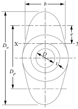
In order to find the flange thickness(tf) we need the width (b) of the oval shape.
To find out this parameter we need to draw an oval shape outline based on the available dimensions.

We have the outer diameter of the flange as major axis Do, the pitch circle diameter Dp, pipe diameter(D) and the thickness (t), we have to draw the above profile and need to measure the parameter b.
Then we get b = 89 mm and the e = 33 mm
From the equation (e) we have Fb×e = σb × (1/6) × b (tf)2.
By substituting all the values we have, we can obtain the flange thickness tf
Fb×e = σb × (1/6) × b (tf)2
13471.5 × 33 = 20 × (1/6) × 89 × (tf)2
(tf)2 = 1500
tf = 38.7mm
Let us take the flange thickness tf as 40mm.
with this flange thickness, we have all the necessary values to design the Oval Flanged pipe joint. If you have any thoughts let us know in the comment sections below.
Square Flanged Pipe Joint
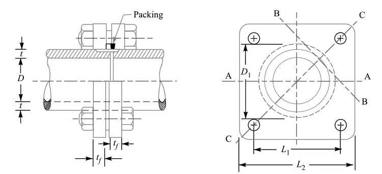
By the way for Square Flanged pipe joint also use the same procedure. except the total load will be divided by four bolts, and the bending moment section will be about the A-A as shown in the below schematic diagram for the Square flanged pipe Joint.

The rest of the design parameters will be almost the same. Let us know if you have any doubts in the comment section. I will help you.

Leave a Reply