In the previous article, we have discussed that from a given torque we can calculate the shaft diameter, but what if the shaft is subjected to the bending moment and twisting at the same time? Let us see how we can calculate shaft diameter under the twisting and bending moment.

Design of Shafts
The design of shafts basically depends on the strength, rigidity, and stiffness. The calculation of the shaft diameter discussed in this article is based on strength of the shaft.
Generally, the shafts are used as either transmission shafts or machine shafts.
Transmission shafts:
Transmission shafts are the ones that transmit the power between the driver and the driven equipment. So all these shafts will be subjected to the twisting load.
Examples of Transmission shafts are the countershafts, line shafts, overhead shafts, and all factory shafts. All of these shafts may contain gears, pully, or stubs.
Due to these elements, the shafts also experience the Bending moments.
Machine shafts are the integral parts of the machine such as the crankshaft.
There are three possible ways that a shaft can experience stress. Those are
- Shear stress due to the twisting or the torque.
- Bending stresses (tensile or compressive) due to the forces acting up on machine elements like gears, pulleys etc. as well as due to the weight of the shaft itself.
- Stresses due to combined torsional and bending loads.
The first case is already discussed in the previous article, but we will see it again one more time.
1. Calculating Shaft Diameter under Twisting load (Motor shafts)
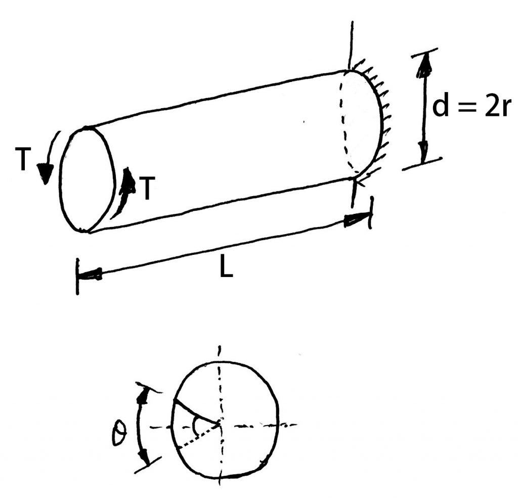
As we know Torsional equation
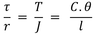
From Torsion Equation we directly write the following expression for the Torque

This relation can be further expanded as follows by substituting the polar moment of inertia of the circular section
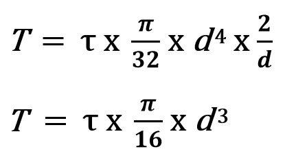
With this relation, we can calculate the shaft diameter if the shaft is only subjected to pure twisting load.
What If there is a bending moment to consider?
Let us see how to calculate the shaft diameter if the shaft is subjected to bending.
2. Calculating Shaft Diameter under Bending Moment only (Axle Shafts)
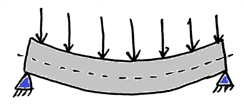
Similar to the torsion Equation, we have a bending equation,

Where
M = Bending Moment
I = Moment of inertia of the shaft
σb = Bending stress
y = Distance of the point from the neutral axis = d/2
E = Modulus elasticity of the material
R = Radius of curvature
From this, we can consider the following portion of the equation.
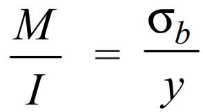
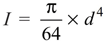
We know that for around solid shaft, a moment of inertia
Let us substitute and get the bending moment relation for the shaft
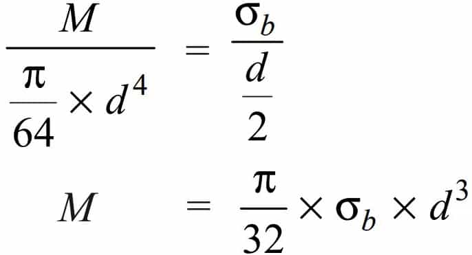
From this relation, we can calculate solid shaft diameter (d) if we have the permissible bending stress and the allowable bending moment of the shaft material.
If the shaft is to be a hallow shaft then we can derive the relation as follows.
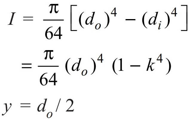
where k = di / do
Again substituting these values in the main bending equation will get us the final expression


From this expression, we can calculate the hollow shaft outer diameter (do) if we have the permissible bending stress and the allowable bending moment of the shaft material.
Do you know where this Bending Moment is only used to calculate the shaft diameter?
To calculate the axels shaft diameter of railway wagon which will have the bending moment only. To calculate the axle shaft diameters of a railway wagon or similar wheel applications, we need to use this approach. Let us solve an example problem to understand how to calculate the axle shaft diameter.
Example problem to calculate the Axle shaft diameter of a Railway wagon
A pair of wheels of a railway wagon carries a load of 50 kN on each axle box, acting at a distance of 100 mm outside the wheelbase. The gauge of the rails is 1.4 m. Find the diameter of the axle between the wheels, if the stress is not to exceed 100 MPa.
Answer:
Given : W = 50 kN = 50 × 103 NL = 100 mm ; x = 1.4 m ; σb = 100 MPa = 100 N/mm2
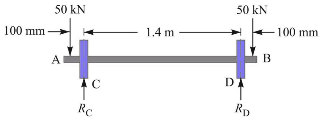
A little consideration will show that the maximum bending moment acts on the wheels at C and D.
Therefore maximum bending moment calculated as follows
RC = RD = 50kN = 50×103N
Bending moment at A is MA = 0
Bending moment at C is MC = 50×103 × 100 = 5×10⁶ N-mm
Bending moment at D is MD = 50×103 × 1500 – 50×103 ×1400 = 5×10⁶ N-mm = 5×10⁶ N-mm
Bending moment at B is MB =0
Overall bending moment (M) = W.L = 50 × 103 × 100 = 5 × 10⁶ N-mm
Let us say d = Diameter of the axle.
We know that the maximum bending moment for a solid shaft is

5 × 106 = π /32 ×σb × d3
= π /32 ×100 × d3
= 9.82 d3
d3 = 5 × 10⁶ / 9.82
= 0.51 × 10⁶
d = 79.8
We got the axle shaft diameter as 79.8mm, let us take the shaft diameter as 80mm.
Now let us consider that the shaft will experience both the Twisting Moment and Bending Moment.
3. Calculating Shaft Diameter under Twisting Moment and Bending Moment
As we mentioned all the transmitting shafts will experience the twisting moment due to the torque and the bending moment due to the machine elements such as gears stubs, and pulleys or in some cases due to the shaft self-weight.
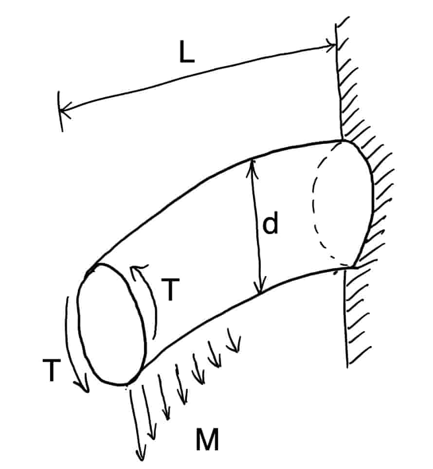
If the shaft is subjected to bending and twisting moments it must be designed on the basis of these two moments simultaneously.
Various theories have been suggested to account for the elastic failure of the materials when they are subjected to various types of combined stresses.
The following two theories are important from the subject point of view :
- Maximum shear stress theory or Guest’s theory. It is used for ductile materials such as mild steel.
- Maximum normal stress theory or Rankine’s theory. It is used for brittle materials such as cast iron.
as we have already assumed above
τ = Shear stress induced due to twisting moment, and
σb = Bending stress (tensile or compressive) induced due to bending moment.
According to maximum shear stress theory, the maximum shear stress in the shaft is

We can Substitute the values of τ and σb as we have discussed above we can get
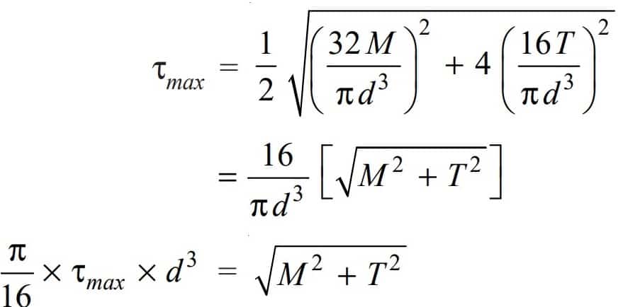
The following expression is known as equivalent twisting moment and is denoted by Te.
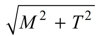
The equivalent twisting moment may be defined as that twisting moment, which when acting alone, produces the same shear stress (τ) as the actual twisting moment.
By limiting the maximum shear stress (τmax) equal to the allowable shear stress (τ) for the material, Let us rewrite the whole above equation

From this relation, we can calculate the shaft diameter (d) under an equivalent twisting moment.
According to maximum normal stress theory, the maximum normal stress in the shaft will be
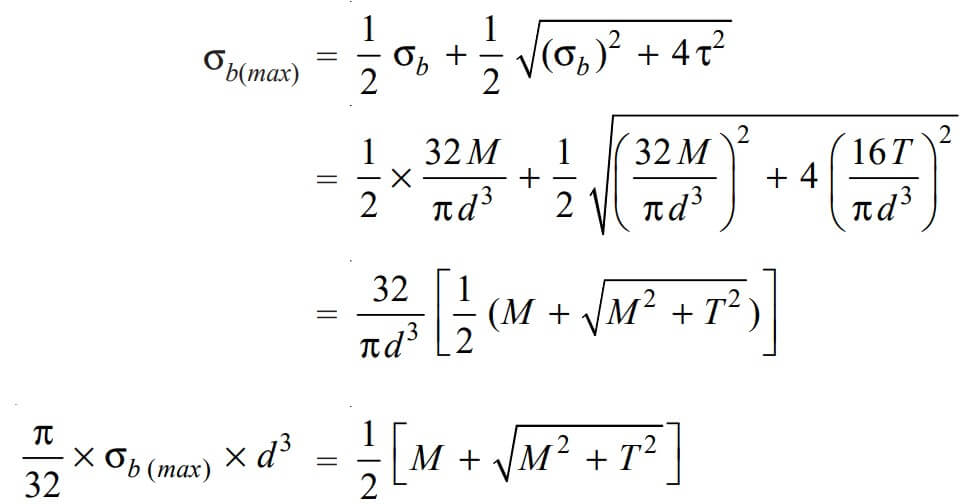
The following expression is known as equivalent bending moment and is denoted by Me

The equivalent bending moment may be defined as that moment which when acting alone produces the same tensile or compressive stress (σb) as the actual bending moment.
By limiting the maximum normal stress [σb(max)] equal to the allowable bending stress (σb), Let us rewrite the whole above equation

From this relation, we can calculate the shaft diameter (d) under an equivalent bending moment.
For Hallow shafts
In the case of a hollow shaft, the above two equations of equivalent twisting and bending moment can be derived as follows.

In order to calculate the shaft diameter under Twisting Moment and Bending Moment, we need to calculate the shaft diameter from the above both equations individually and the larger shaft diameter is supposed to be used for the design of the shaft.
Let us take an example problem and see how we can calculate the shaft diameter under Twisting Moment and Bending Moment and choose the right size of the shaft.
Example Problem Calculating Shaft Diameter under Twisting Moment and Bending Moment
A solid circular shaft is subjected to a bending moment of 3000N-m and a torque of 10000N-m. The shaft is made of 45 C 8 steel having ultimate tensile stress of 700MPa and ultimate shear stress of 500MPa. Taking a factor of safety as 6 into account, calculate the shaft diameter.
Answer:
Given data
Bending moment (M) = 3000N-m = 3 × 10⁶ N-mm
Torque (T) = 10000 N-m = 10 × 106 N-mm
ultimate tensile stress σtu = 700 MPa = 700 N/mm2
shear stress τu = 500 MPa = 500 N/mm2
Factor of Safety = 6
We know that the allowable tensile stress, σt or σb = σtu/ F.S = 700/6 = 116.7N/mm2
and allowable shear stress τ = τu / F.S = 500/6 = 83.3N/mm2
These are the actual allowable stress after taking the factor of safety into account.
Now let us take d = Diameter of the shaft in mm.
According to maximum shear stress theory, equivalent twisting moment relation and substituting the given values are as follows.

√((3×10⁶)2 +(10×106)2) = (π/16) × 83.3 × d3
10.44×106 = 16.36 d3
d3 = 10.44 × 10⁶ / 16.36
d3 = 0.636 × 10⁶
d = 86 mm
We have got the shaft diameter as 86mm according to the maximum shear stress theory. Let us also calculate the shaft diameter according to the maximum normal stress theory.
According to maximum normal stress theory, equivalent bending moment relation, and substituting the given values are as follows.

(1/2) × [3×106 + √((3×10⁶)2 +(10×106)2)] = (π/16) × 116.7 × d3
6.72×106 = 11.46 × d3
d 3 = 6.72 × 10⁶ / 11.46
d 3 = 0.586 × 10⁶
d = 83.7 mm
by considering the maximum normal stress theory, we get the shaft diameter of 83.7mm.
The largest of the two stress theories is 86mm from the maximum shear stress theory.
86mm is a safe value to consider for designing the shaft. It is better to take the standard values of the shaft.
Standard shaft Diamters for transmission shafts
Following are the available standard shaft diameters
- Shaft diameter 25mm to 60mm with 5mm steps (25, 30, 35, 40, 45, 50, 55, 60)
- Shaft diameter 60mm to 110mm with 10mm steps (60, 70, 80, 90, 100,110)
- Shaft diameter 110mm to 140mm with 15mm steps (110, 125, 140)
- Shaft diameter 140mm to 500mm with 20mm steps (140, 160, 180, 200, 220, 240, 260, 280, 300, 320, 340, 360, 380, 400,, 420, 440, 460, 480, 500)
The standard shaft lengths available are 5 meters, 6 meters, and 7 meters.
For our above problem, we got the shaft dia as 86mm, so the next available size is 90mm shaft. we need to take the shaft 90mm dia shaft to design the shaft.
We have discussed how to calculate the shaft diameter under the Twisting and Bending Moment. But these twisting moments and the bending moment are assumed to be constant for the sake of calculating shaft diameter.
But in actual practice, the shafts will be subjected to fluctuating torque and bending moments.
Calculate Shaft Diameter under Fluctuating Load
The Fluctuating load will be a real-life scenario that we can not avoid in designing a shaft. so we need to calculate the shaft diameter under Fluctuating Load. These kinds of fluctuating loads will be seen in the Line shafts and the Counter shafts.
In order to design such shafts like line shafts and counter shafts, the combined shock and fatigue factors must be taken into account to calculate the shaft diameter.
Thus for a shaft subjected to combined fluctuated bending and torsion, the equivalent twisting moment,

and equivalent fluctuated bending moment,

where
Km = Combined shock and fatigue factor for bending
Kt = Combined shock and fatigue factor for torsion.
The above equivalent twisting moment and bending and bending moment needs to be equated with the above formulas and can calculate the shaft diameter.
The following table shows the recommended values for Km and Kt
| Nature of load | Km | Kt |
| 1. Stationary shafts | ||
| (a) Gradually applied load | 1 | 1 |
| (b) Suddenly applied load | 1.5 to2.0 | 1.5 to 2.0 |
| 2. Rotating shafts | ||
| (a) Gradually applied or steady load | 1.5 | 1 |
| (b) Suddenly applied load with minor shocks only | 1.5 to2.0 | 1.5 to 2.0 |
| (c) Suddenly applied load with heavy shocks | 2.0 to 3.0 | 1.5 to 3.0 |
Conclusion
We have discussed different types of shafts, are transmission shafts and machine shafts. And discussed How to calculate Shaft diameter under twisting and Bending moment, with fluctuating load and solved a sample problem also. Listed the different standard shaft diameters to select from. Also listed are the criteria for deciding the diameter of a shaft used in power transmission. Let us know what do you think about this in the comment section below.
I would like you to solve a small sample problem given below.
Problem statement: A shaft made of mild steel is required to transmit 100 kW at 300 r.p.m. The supported length of the shaft is 3 metres. It carries two pulleys each weighing 1500 N supported at a distance of 1 meter from the ends respectively. Assuming the safe value of stress, determine the diameter of the shaft.
Let me know the answer in the comment section below. I will help you.

Problem Statement: A steel solid shaft transmitting 15 kW at 200 RPM is supported on two bearings 750 mm apart and has two gears keyed to it. The pinion having 30 teeth of a 5 mm module is located 100 mm to the left of the right-hand bearing and delivers power horizontally to the right. The gear having 100 teeth of 5 mm module is located 150 mm to the right of the left-hand bearing and receives power in a vertical direction from below. Using allowable stress of 54 MPa in shear, determine the diameter of the shaft.
This is a somewhat complex problem. It involves finding the bending moment and drawing bending moment diagrams as well. Try to solve it.
Check here for the answer: https://extrudesign.com/example-problem-on-calculating-shaft-diameter/