A spring is defined as an elastic body, whose function is to distort when loaded and to recover its original shape when the load is removed. It absorbs or controls energy due to either shock or vibration so it can be used as shock absorbers and vibration dampers. It is also used to apply forces, as in brakes, clutches, and spring-loaded valves. We have discussed different types of Springs. We also discussed the Stresses in Helical Springs of circular Wire and non-circular wire in the previous article. Let us discuss the Helical Springs Subjected to Fatigue Loading.
Applications of Springs
The various important applications of springs are as follows:
- To cushion, absorb, or control energy due to either shock or vibration as in car springs, railway buffers, aircraft landing gears, shock absorbers, and vibration dampers.
- To apply forces, as in brakes, clutches, and spring-loaded valves.
- To control motion by maintaining contact between two elements as in cams and followers.
- To measure forces, as in spring balances and engine indicators.
- To store energy, as in watches, toys, etc.
Types of Springs
Though there are many types of springs, the following, according to their shape, are important from the subject point of view.
- Helical springs
- Conical and volute springs
- Torsion springs
- Laminated or leaf springs
- Disc or Belleville springs
- Special-purpose springs
We have discussed more details in a separate article here!
we also discussed the Stresses in Helical Springs of circular Wire and non-circular wire in the previous article.
Helical Springs Subjected to Fatigue Loading
The helical springs subjected to fatigue loading are designed by using the Soderberg line method. The spring materials are usually tested for torsional endurance strength under repeated stress that varies from zero to maximum. Since the springs are ordinarily loaded in one direction only (the load in springs is never reversed in nature), therefore a modified Soderberg diagram is used for springs, as shown in the following figure.
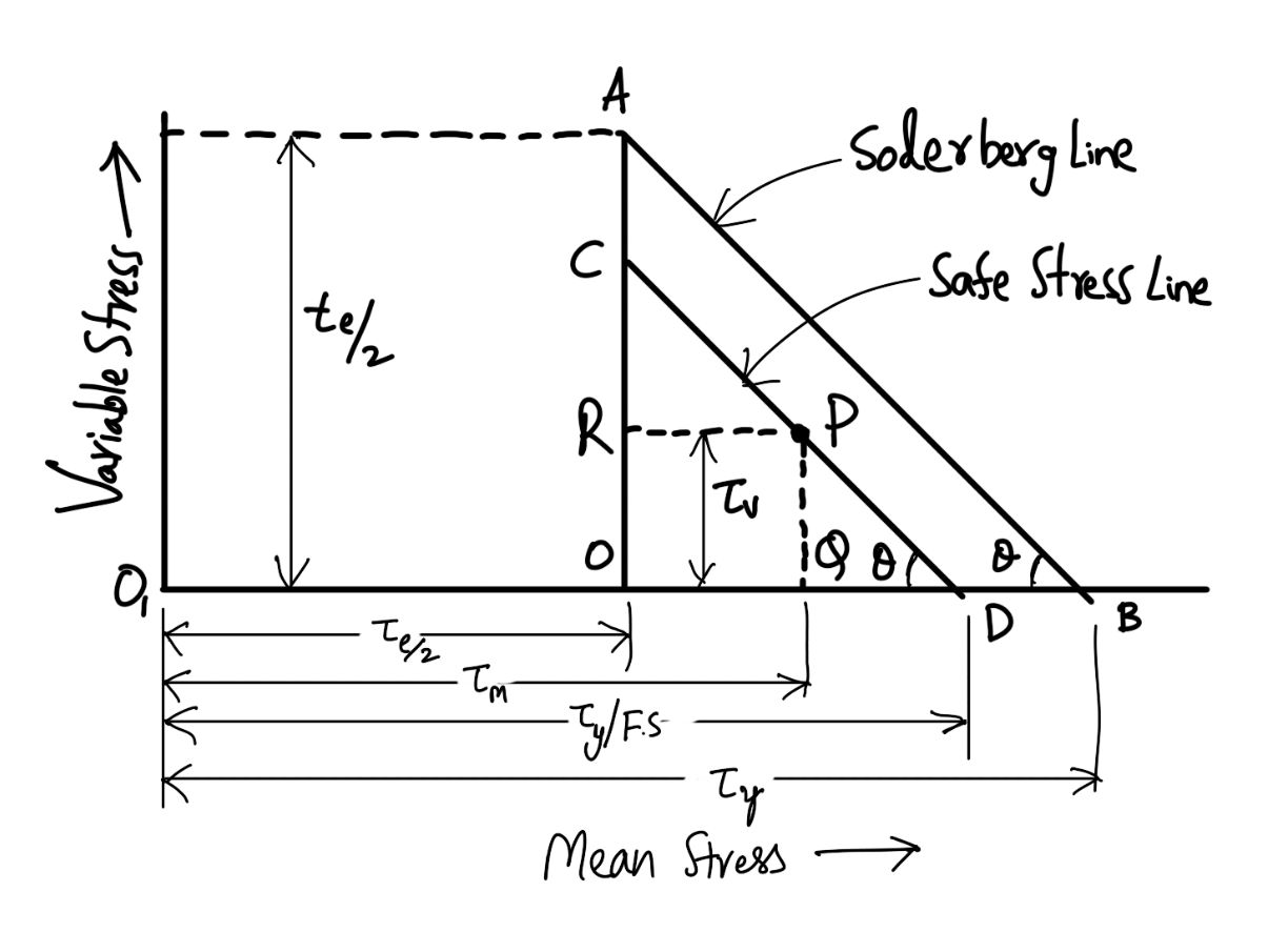
The endurance limit for reversed loading is shown at point A where the mean shear stress is equal to τe / 2 and the variable shear stress is also equal to τe / 2. A line drawn from A to B (the yield point in shear, τy) gives the Soderberg’s failure stress line. If a suitable factor of safety (F.S.) is applied to the yield strength (τy), a safe stress line CD may be drawn parallel to the line AB, as shown in the above figure. Consider a design point P on the line CD.
Now the value of the factor of safety may be obtained as discussed below:
From similar triangles PQD and AOB, we have
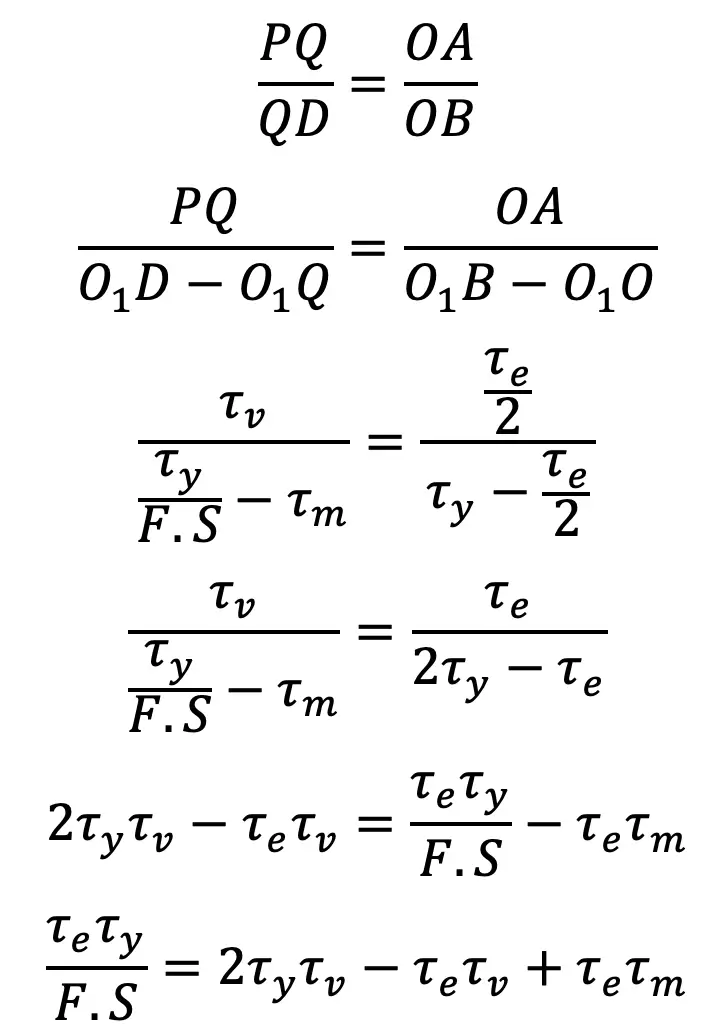
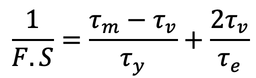
By dividing both sides by τe.τy and rearranging, we have
👉 Important Notes:
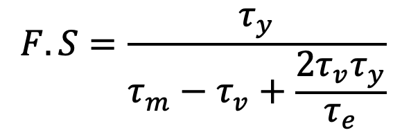
1. From the above factor of safety equation, the expression for the factor of safety (F.S.) may be written as
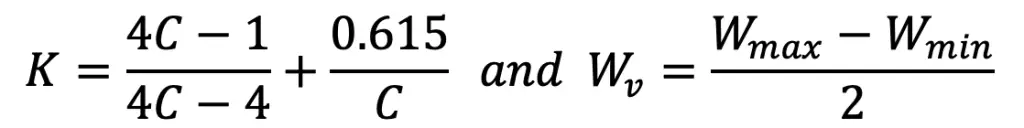
2. The value of mean shear stress (τm) is calculated by using the shear stress factor (KS), while the variable shear stress is calculated by using the full value of Wahl’s factor (K). Thus
Mean shear stress,
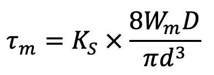
Where
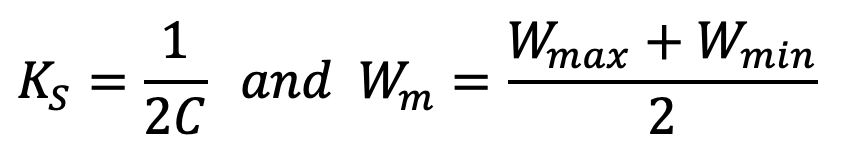
and variable shear stress,
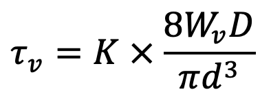
where
This is all about the Helical Springs Subjected to Fatigue Loading. Let us know what you think about this article in the comment section below.
Leave a Reply