A spring is defined as an elastic body, whose function is to distort when loaded and to recover its original shape when the load is removed. It absorbs or controls energy due to either shock or vibration so it can be used as shock absorbers and vibration dampers. It is also used to apply forces, as in brakes, clutches, and spring-loaded valves. We have already discussed different types of Springs in the previous article. Let us discuss the different Stresses in Helical Springs of Circular Wire.
Applications of Springs
The various important applications of springs are as follows:
- To cushion, absorb, or control energy due to either shock or vibration as in car springs, railway buffers, aircraft landing gears, shock absorbers, and vibration dampers.
- To apply forces, as in brakes, clutches, and spring-loaded valves.
- To control motion by maintaining contact between two elements as in cams and followers.
- To measure forces, as in spring balances and engine indicators.
- To store energy, as in watches, toys, etc.
Types of Springs
Though there are many types of springs, the following, according to their shape, are important from the subject point of view.
- Helical springs
- Conical and volute springs
- Torsion springs
- Laminated or leaf springs
- Disc or Belleville springs
- Special-purpose springs
We have discussed more details in a separate article here!
Stresses in Helical Springs of Circular Wire
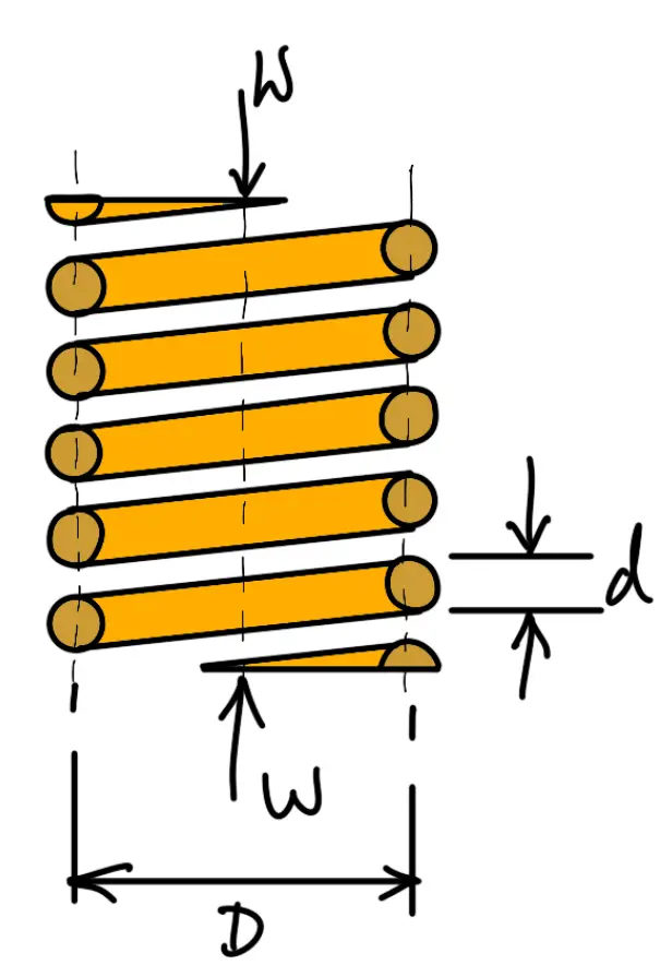
In Helical springs, the major type of stress-induced is the torsional shear stress due to twisting. Let us only consider these Stresses in Helical Springs of Circular Wire. Consider a helical compression spring made of circular wire and subjected to an axial load W, as shown in the following figure.
Let
D = Mean diameter of the spring coil
d = Diameter of the spring wire
n = Number of active coils
G = Modulus of rigidity for the spring material
W = Axial load on the spring
τ = Maximum shear stress induced in the wire
C = Spring index = D/d
p = Pitch of the coils
δ = Deflection of the spring, as a result of an axial load W
Now consider a part of the compression spring as shown in the following figure. The load W tends to rotate the wire due to the twisting moment (T) set up in the wire. Thus torsional shear stress is induced in the wire.
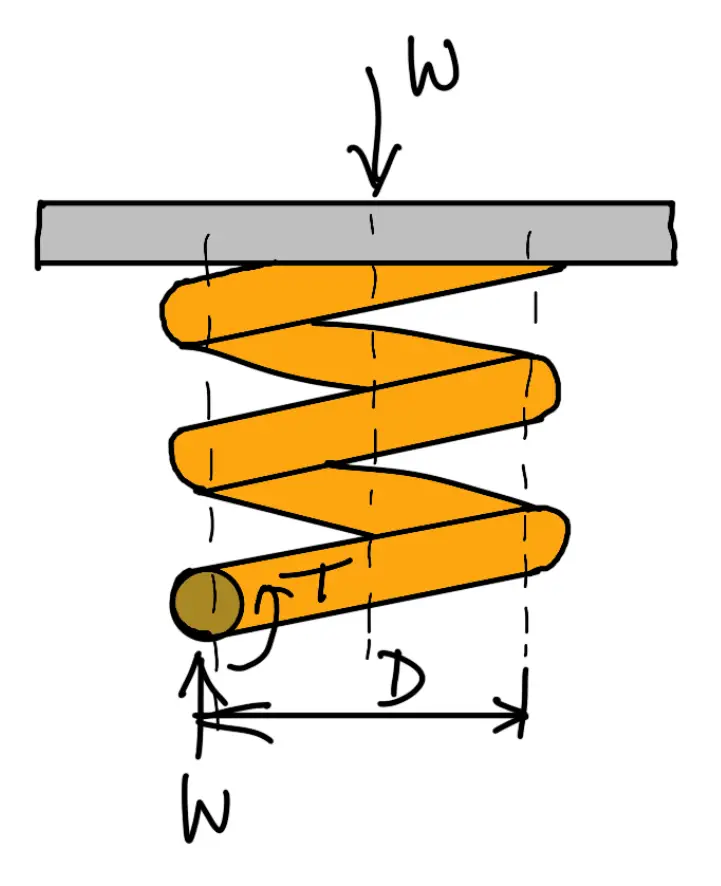
A little consideration will show that part of the spring, as shown in the above figure, is in equilibrium under the action of two forces W and the twisting moment T. We know that the twisting moment,

The torsional shear stress is
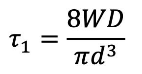
The torsional shear stress diagram is shown in the following figure.
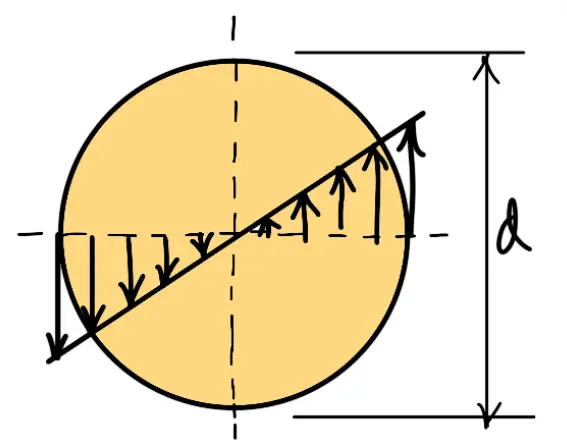
In addition to the torsional shear stress (τ1) induced in the wire, the following stresses also act on the wire:
- Direct shear stress due to the load W,
- Stress due to curvature of wire.
We know that direct shear stress due to the load W,
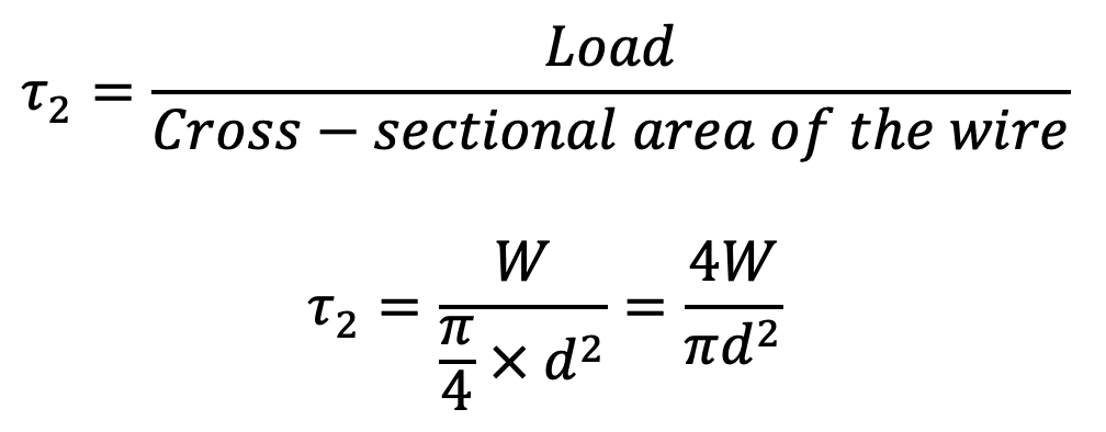
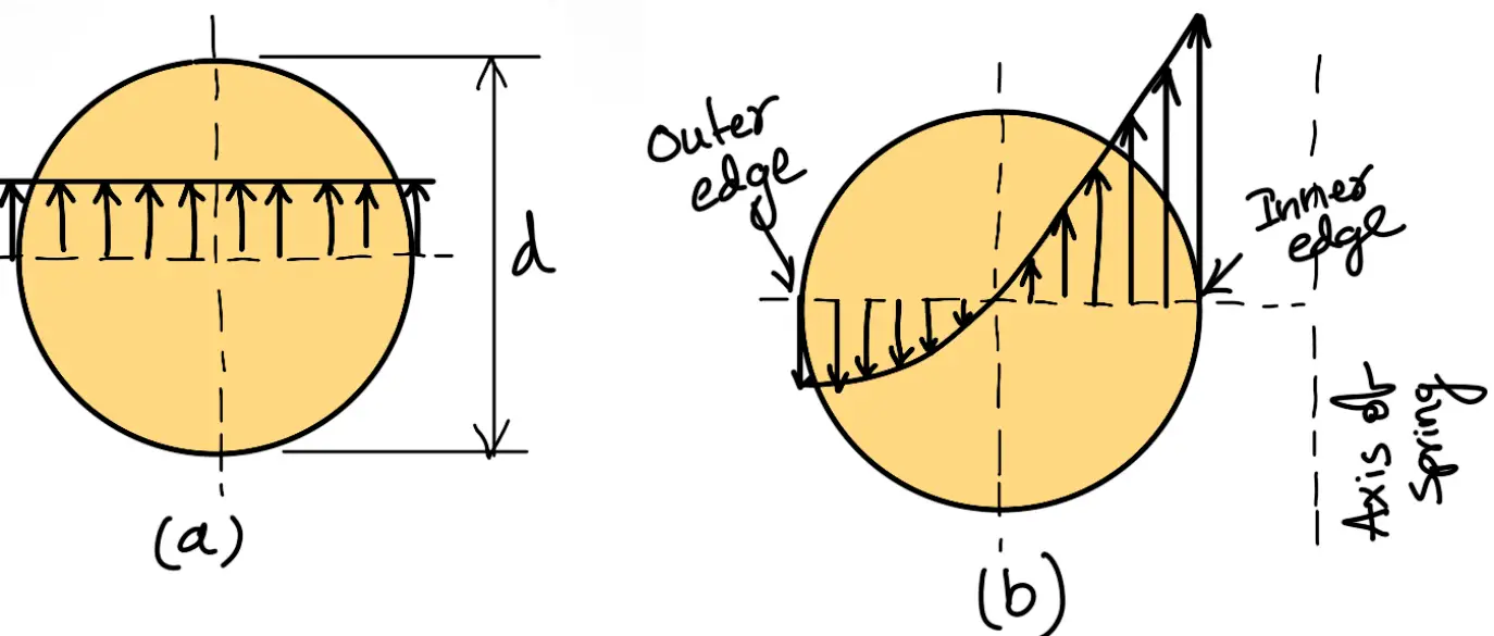
The direct shear stress diagram is shown in the following figure (a) and the resultant diagram of torsional shear stress and direct shear stress is shown in the following figure (b).
We know that the resultant shear stress induced in the wire,
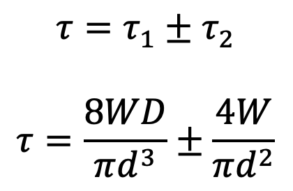
The positive sign is used for the inner edge of the wire and the negative sign is used for the outer edge of the wire. Since the stress is maximum at the inner edge of the wire, therefore
Maximum shear stress induced in the wire = Torsional shear stress + Direct shear stress
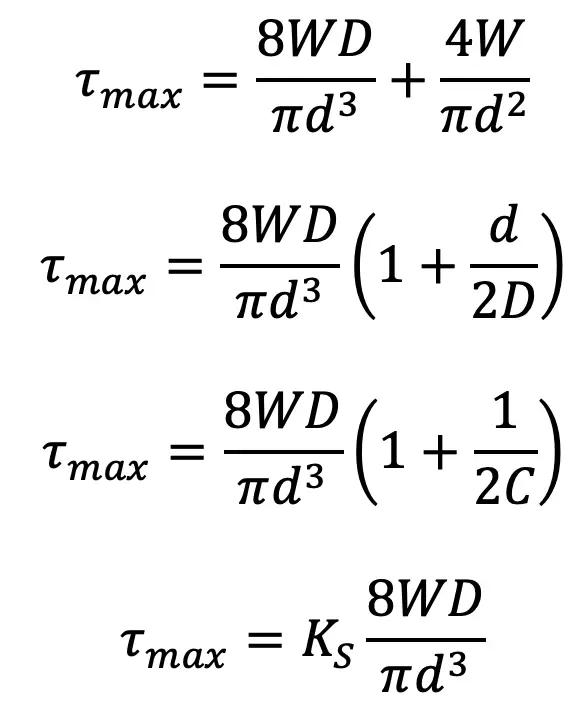
Where
KS = Shear stress factor
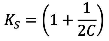
From the above equation, it can be observed that the effect of direct shear is
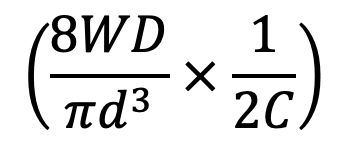
and it is appreciable for springs of small spring index C. Also, we have neglected the effect of wire curvature in the above Maximum shear stress equation. It may be noted that when the springs are subjected to static loads, the effect of wire curvature may be neglected because yielding of the material will relieve the stresses.
To consider the effects of both direct shear as well as curvature of the wire, a Wahl’s stress factor (K) introduced by A.M. Wahl may be used. The resultant diagram of torsional shear, direct shear, and curvature shear stress is shown in the following figure.
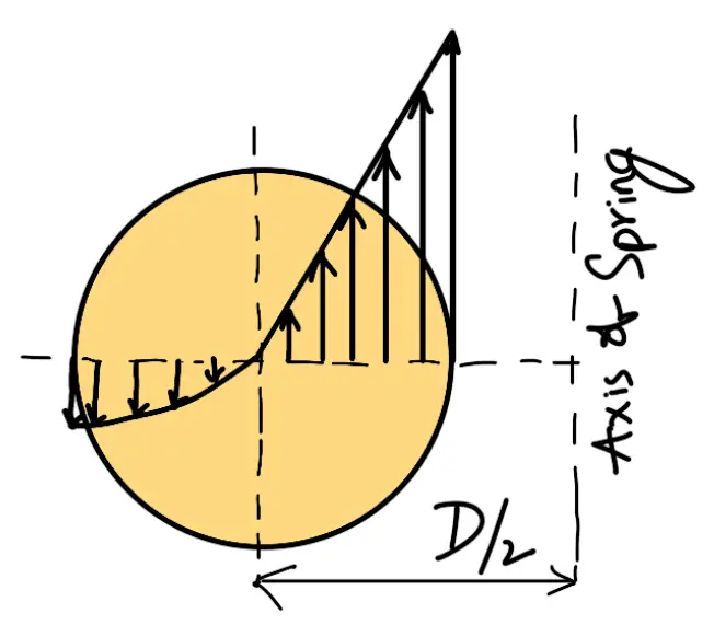
∴ Maximum shear stress induced in the wire,

where

The values of K for a given spring index (C) may be obtained from the graph as shown below.
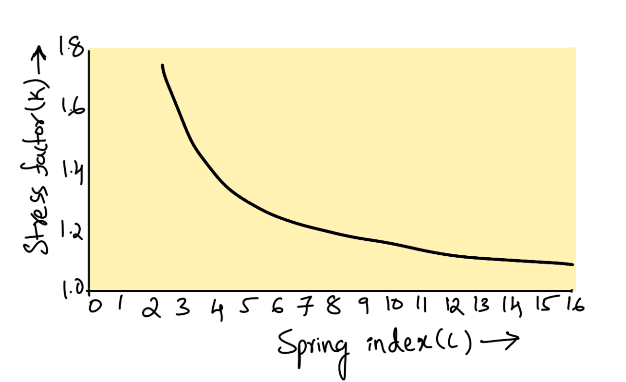
We see from the above graph that Wahl’s stress factor increases very rapidly as the spring index decreases. The spring mostly used in machinery has a spring index above 3.
👉 Important Note:
The Wahl’s stress factor (K) may be considered as composed of two sub-factors, KS and KC, such that
K = KS × KC
Where
KS = Stress factor due to shear,
KC = Stress concentration factor due to curvature.
Deflection of Helical Springs of Circular Wire
In the previous article, we discussed the maximum shear stress developed in the wire. We know that
Total active length of the wire l = Length of one coil × Number of active coils
l = π D × n
Let θ = Angular deflection of the wire when acted upon by the torque T.
∴ Axial deflection of the spring,
δ = θ × D / 2
We also know the torsion equation
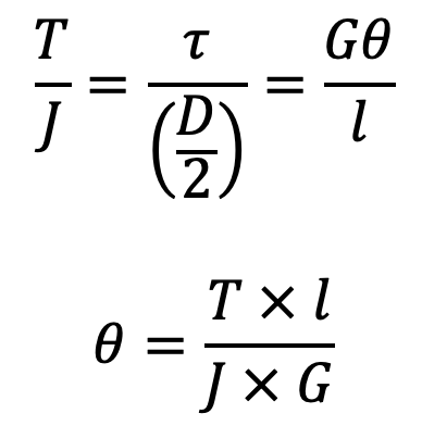
where
J = Polar moment of inertia of the spring wire = (π/32)×d2
d = Diameter of spring wire
G = Modulus of rigidity for the material of the spring wire.
Now substituting the values of l and J in the above equation, we have
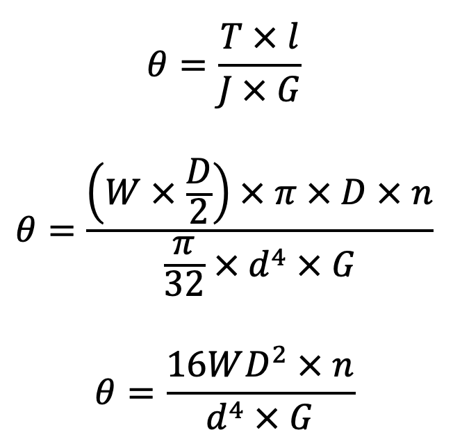
Bow let us substitute this value of θ in equation δ = θ × D / 2 we get

and the stiffness of the spring or spring rate,

Eccentric Loading of Springs
Sometimes, the load on the springs does not coincide with the axis of the spring, i.e. the spring is subjected to an eccentric load. In such cases, not only the safe load for the spring reduces, the stiffness of the spring is also affected. The eccentric load on the spring increases the stress on one side of the spring and decreases on the other side. When the load is offset by a distance e from the spring axis, then the safe load on the spring may be obtained by multiplying the axial load by the factor
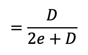
where D is the mean diameter of the spring.
This is all about the different Stresses in Helical Springs of Circular Wire. Let us know what you think about this article in the comment section below.

Leave a Reply