We have discussed belt drives and rope drives that slipping may occur. To avoid slipping, steel chains are used. The chains are made up of a number of rigid links which are hinged together by pin joints to provide the necessary flexibility for wrapping around the driving and driven wheels. These wheels have projecting teeth of special profile and fit into the corresponding recesses in the links of the chain. The toothed wheels are known as sprocket wheels or simply sprockets (These wheels resemble spur gears). The sprockets and the chain are thus constrained to move together without slipping, ensuring a perfect velocity ratio. We have already discussed Chain Drive Terminology, Classification, and Advantages in the previous article. Let us discuss the Design Procedure of Chain Drive.

Chain Drive: Chains and Sprockets
The chains are mostly used to transmit motion and power from one shaft to another when the center distance between their shafts is short such as in bicycles, motorcycles, agricultural machinery, conveyors, rolling mills, road rollers, etc. The chains may also be used for long center distances of up to 8 meters. The chains are used for velocities up to 25m/s and power up to 110 kW. In some cases, higher power transmission is also possible.
Following is a schematic Representation of a Chain Drive that comprises Sprockets and a chain.
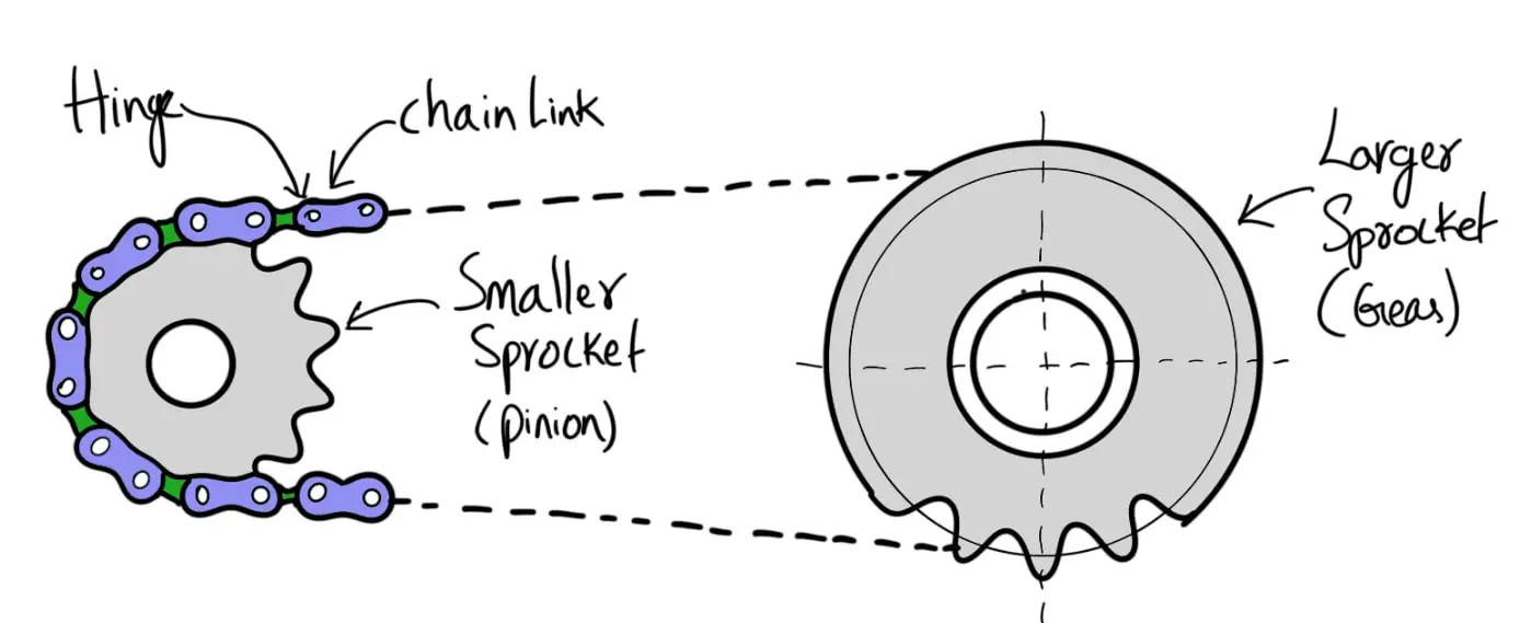
We have also discussed how we can calculate the Length of Chain and Centre Distance, and Power Transmitted by chains.
Now let us discuss the Design Procedure of Chain Drive.
Design Procedure of Chain Drive
- Determine the Velocity Ratio of Chain Drives
- Select the minimum number of teeth on the smaller sprocket or pinion
- Find the number of teeth on the larger sprocket.
- Determine the design power by using the service factor, such that
Design power = Rated power × Service factor - Choose the type of chain, number of strands for the design power, and r.p.m. of the smaller sprocket
- Note down the parameters of the chain, such as pitch, roller diameter, minimum width of roller, etc.
- Find the pitch circle diameters and pitch line velocity of the smaller sprocket.
- Determine the load (W) on the chain by using the following relation
- Calculate the factor of safety by dividing the breaking load (WB) by the load on the chain (W).
- Fix the center distance between the sprockets.
- Determine the length of the chain.
- The other dimensions may be calculated as we discussed further in this article.
Let us Discuss each of these steps in detailed manner for Design Procedure of Chain Drive.
1. Determine the Velocity Ratio of Chain Drives
The velocity ratio of a chain drive is given by
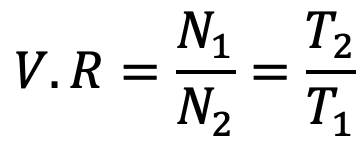
Where
N1 = Speed of rotation of smaller sprocket in r.p.m
N2 = Speed of rotation of larger sprocket in r.p.m
T1 = Number of teeth on the smaller sprocket
T2 = Number of teeth on the larger sprocket
The average velocity of the chain is given by
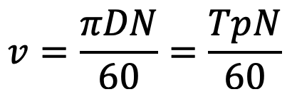
Where
D = Pitch circle diameter of the sprocket in meters
p = Pitch of the chain in meters
2. Select the minimum number of teeth on the smaller sprocket or pinion
Consider an arrangement of a chain drive in which the smaller or driving sprocket has only four teeth, as shown in the following figure.
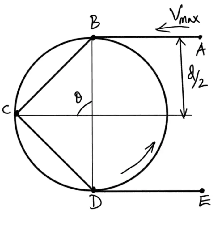
Let the sprocket rotates anticlockwise at a constant speed of N r.p.m. The chain link AB is at a distance of d/2 from the center of the sprocket and its linear speed is given by

where d = Pitch circle diameter of the smaller or driving sprocket in meters.
When the sprocket rotates through an angle θ/2, the link AB occupies the position as shown in the following figure.
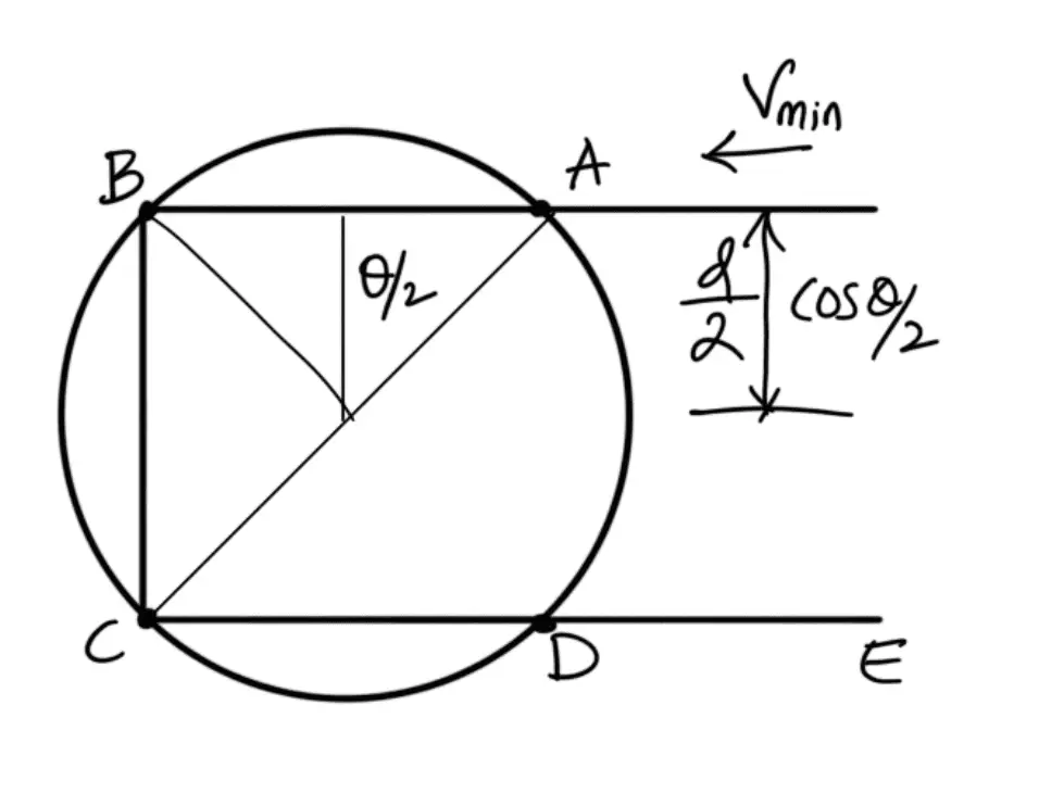
From the figure, we see that the link is now at a distance of ( (d/2) × cos (θ/2) ) from the center of the sprocket, and its linear velocity is given by

From above, we see that the linear velocity of the sprocket is not uniform but varies from maximum to minimum during every cycle of tooth engagement. This results in fluctuations in chain transmission and may be minimized by reducing the angle θ or by increasing the number of teeth on the sprocket. It has been observed that for a sprocket having 11 teeth, the variation of speed is 4 percent and for the sprockets having 17 teeth and 24 teeth, the variation of speed is 1.6 percent and 1 percent respectively.
To have a smooth operation, the minimum number of teeth on the smaller sprocket or pinion may be taken as 17 for moderate speeds and 21 for high speeds. The following table shows the number of teeth on a smaller sprocket for different velocity ratios.
Table: Number of teeth on the smaller sprocket.
| Type of chain | Number of teeth at velocity ratio | |||||
| 1 | 2 | 3 | 4 | 5 | 6 | |
| Roller | 31 | 27 | 25 | 23 | 21 | 17 |
| Silent | 40 | 35 | 31 | 27 | 23 | 19 |
Note: The number of teeth on the smaller sprocket plays an important role in deciding the performance of a chain drive. A small number of teeth tends to make the drive noisy. A large number of teeth makes the chain pitch smaller which is favorable for keeping the drive silent and reducing shock, centrifugal force, and friction force.
3. Find the number of teeth on the larger sprocket.
From the Velocity ratio relation, we have from the above,

we can find the teeth on the larger sprocket.
4. Determine the design power by using the service factor
The power transmitted by the chain based on the breaking load is given by

The power transmitted by chains based on the bearing stress is given by
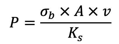
Where
Wb = Breaking load in newtons
σb = Allowable bearing stress in MPa or N/mm2
v = Velocity of chain in m/s
n = Factor of safety
Ks = Service factor = K1 .K2 .K3
The service factor (KS) is the product of various factors, such as load factor (K1), lubrication factor (K2), and rating factor (K3). The values of these factors can be understood from the previous article we discussed.
5. Choose the type of chain, number of strands for the design power, and r.p.m. of the smaller sprocket
Based on the power rating we got from the above step we can select the simple roller chains depending on the speed of the smaller sprocket is shown in the following table.
| Speed of smaller sprocket or pinion (r.p.m.) | Power (kW) | ||||
| 06 B | 08 B | 10 B | 12 B | 16 B | |
| 100 200 300 500 700 1000 1400 1800 2000 | 0.25 0.47 0.61 1.09 1.48 2.03 2.73 3.44 3.80 | 0.64 1.18 1.70 2.72 3.66 5.09 6.81 8.10 8.67 | 1.18 2.19 3.15 5.01 6.71 8.97 11.67 13.03 13.49 | 2.01 3.75 5.43 8.53 11.63 15.65 18.15 19.85 20.57 | 4.83 8.94 13.06 20.57 27.73 34.89 38.47 – – |
6. Note down the parameters of the chain, such as pitch, roller diameter, minimum width of roller, etc from the following table.
According to Indian Standards (IS: 2403 —1991), the various characteristics such as pitch, roller diameter, width between inner plates, transverse pitch, and breaking load for the roller chains are given in the following table.
Table: Characteristics of roller chains according to IS: 2403 — 1991.
| ISO Chain number | Pitch (p) mm | Roller diameter(d1) mm Maximum | Width between inner plates (b1) mm Maximum | Transverse pitch ( p1 )mm | Breaking load (kN) Minimum | ||
| Simple | Duplex | Triplex | |||||
| 05 B 06 B 08 B 10 B 12 B 16 B 20 B 24 B 28 B 32 B 40 B 48 B | 8.00 9.525 12.70 15.875 19.05 25.4 31.75 38.10 44.45 50.80 63.50 76.20 | 5.00 6.35 8.51 10.16 12.07 15.88 19.05 25.40 27.94 29.21 39.37 48.26 | 3.00 5.72 7.75 9.65 11.68 17.02 19.56 25.40 30.99 30.99 38.10 45.72 | 5.64 10.24 13.92 16.59 19.46 31.88 36.45 48.36 59.56 68.55 72.29 91.21 | 4.4 8.9 17.8 22.2 28.9 42.3 64.5 97.9 129 169 262.4 400.3 | 7.8 16.9 31.1 44.5 57.8 84.5 129 195.7 258 338 524.9 800.7 | 11.1 24.9 44.5 66.7 86.7 126.8 193.5 293.6 387 507.10 787.3 1201 |
7. Find the pitch circle diameters and pitch line velocity of the smaller sprocket.
A chain wrapped around the sprocket is shown in the following figure.
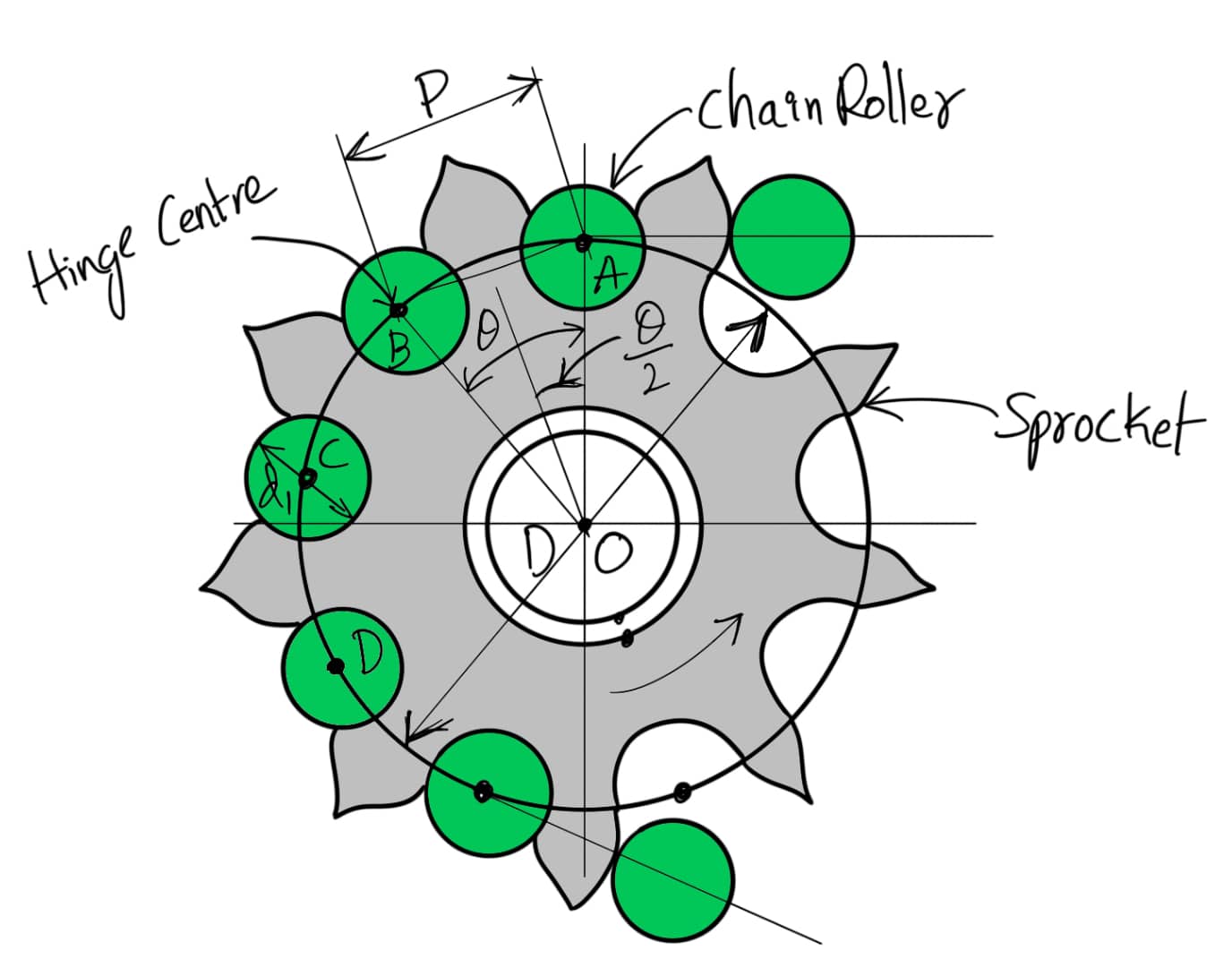
Since the links of the chain are rigid, therefore the pitch of the chain does not lie on the arc of the pitch circle. The pitch length becomes a chord. Consider one pitch length AB of the chain subtending an angle θ at the center of the sprocket (or pitch circle),
D = Diameter of the pitch circle
T = Number of teeth on the sprocket
The relation between pitch and the Pitch circle diameter is given below
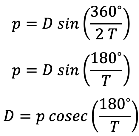
The sprocket outside diameter (Do), for satisfactory operation, is given by
Do = D + 0.8 d1
where d1 = Diameter of the chain roller.
Please note that the angle θ/2 through which the link swings as it enters contact is called the angle of articulation.
Read more about the relationship between Pitch and Pitch circle diameter in a detailed article here.
8. Determine the load (W) on the chain by using the following relation

9. Calculate the factor of safety by dividing the breaking load (WB) by the load on the chain (W).
The factor of safety for chain drives is defined as the ratio of the breaking strength (WB ) of the chain to the total load on the driving side of the chain (W). Mathematically,

The breaking strength of the chain may be obtained by the following empirical relations, i.e.
WB = 106 p2 (in newtons) for roller chains
WB = 106 p (in newtons) per mm width of chain for silent chains.
where p is the pitch in mm.
The total load (or total tension) on the driving side of the chain is the sum of the tangential driving force (FT), centrifugal tension in the chain (FC), and the tension in the chain due to sagging (FS).
We know that the tangential driving force acting on the chain,

Centrifugal tension in the chain,
FC = m.v2 (in newtons)
and tension in the chain due to sagging,
FS = k.mg.x (in newtons)
where
m = Mass of the chain in kg per meter length
x = Centre distance in meters
k = Constant which takes into account the arrangement of the chain drive
= 2 to 6, when the center line of the chain is inclined to the horizontal at an angle less than 40o
= 1 to 1.5, when the center line of the chain is inclined to the horizontal at an angle greater than 40o.
This value of the factor of safety should be greater than the value given in the following table.
| Type of chain | Pitch of chain (mm) | Speed of the sprocket pinion in r.p.m. | ||||||||
| 50 | 200 | 400 | 600 | 800 | 1000 | 1200 | 1600 | 2000 | ||
| Bush roller chain | 12 – 15 20 – 25 30 – 35 | 7 7 7 | 7.88.2 8.55 | 8.55 9.35 10.2 | 9.35 10.3 13.2 | 10.2 11.7 14.8 | 11 12.9 16.3 | 11.7 14 19.5 | 13.2 16.3 – | 14.8 – – |
| Silent chain | 12.7 – 15.87 19.05 – 25.4 | 20 20 | 22.2 23.4 | 24.4 26.7 | 28.7 30.0 | 29.0 33.4 | 31.0 — 33.4 36.8 — 40.0 | 37.8 46.5 | 42.0 53.5 | |
10. Fix the center distance between the sprockets.
Following is an open chain drive system connecting the two sprockets.
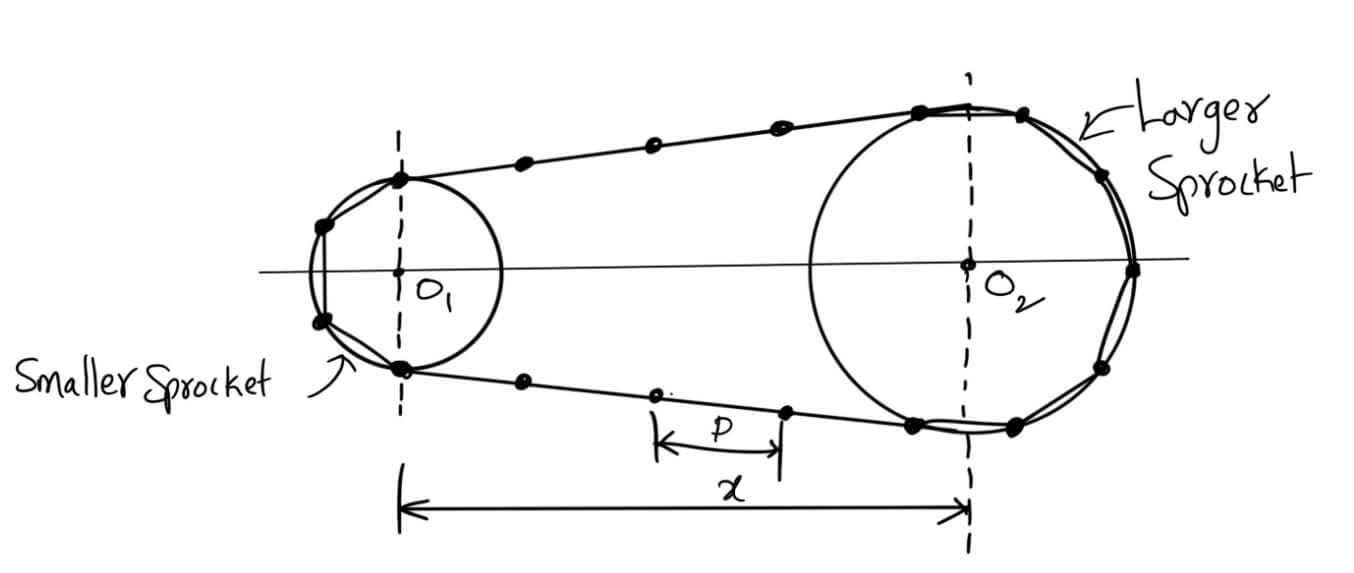
Let
T1 = Number of teeth on the smaller sprocket
T2 = Number of teeth on the larger sprocket
p = Pitch of the chain
x = Centre distance
The length of the chain (L) must be equal to the product of the number of chain links (K) and the pitch of the chain (p).
Mathematically,
L = K.p
The number of chain links may be obtained from the following expression, i.e.

The value of K as obtained from the above expression must be approximated to the nearest even number.
The center distance is given by

To accommodate the initial sag in the chain, the value of the center distance obtained from the above equation should be decreased by 2 to 5 mm.
- The minimum center distance for the velocity transmission ratio of 3, may be taken as
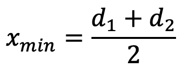
where d1 and d2 are the diameters of the pitch circles of the smaller and larger sprockets.
- For best results, the minimum center distance should be 30 to 50 times the pitch.
- The minimum center distance is selected depending on the velocity ratio so that the arc of contact of the chain on the smaller sprocket is not less than 120∘. It may be noted that a larger angle of the arc of contact ensures a more uniform distribution of load on the sprocket teeth and better conditions of engagement.
11. Determine the length of the chain
from the above-mentioned relation.
L = K.p
Where K = number of chain links and p = Pitch of the chain.
With this most of the parameters are available with the help of this Design Procedure of Chain Drive.
12. The other dimensions of the Chain drive can be determined as follows.
The standard profiles for the teeth of a sprocket are shown in the following figure.
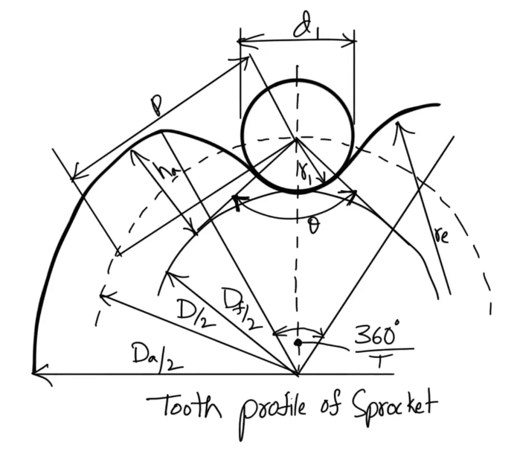
Following are the rim profiles of the sprocket
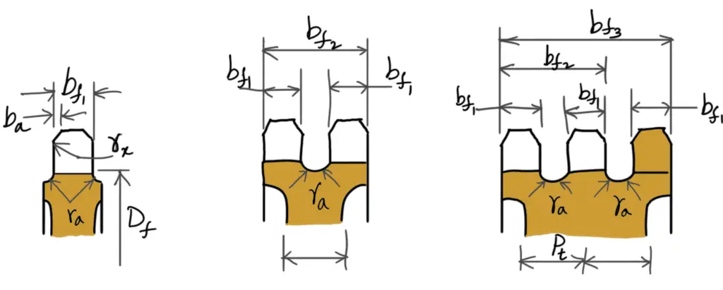
According to Indian Standards (IS: 2403 – 1991), the principal dimensions of the tooth profile are as follows:
1.
Tooth flank radius (re) Maximum = 0.008 d1 (T2 + 180)
Tooth flank radius (re) Minimum = 0.12 d1 (T + 2)
where
d1 = Roller diameter
T = Number of teeth
2.
Roller seating radius(ri) Maximum = 0.505 d1 + 0.069 ∛d1
Roller seating radius(ri) Minimum = 0.505 d1
3.
Roller seating angle(α) Maximum = 140o – 90o/T
Roller seating angle(α) Minimum = 120o – 90o/T
4.
Tooth height above the pitch polygon (ha) Maximum = 0.625 p – 0.5 d1 + 0.8 p / T
Tooth height above the pitch polygon (ha) Minimum = 0.5 ( p — d1)
5. Pitch circle diameter(D)

6.
Top diameter(Da) Maximum = D + 1.25 p – d1
Top diameter(Da) Minimum = D + p (1 – (1.6/T))– d1
7.
Root diameter(Df) = D – 2 ri
8.
Tooth width(bf1) = 0.93b1 when p ≤ 12.7mm
Tooth width(bf1) = 0.95b1 when p > 12.7mm
9. Tooth side radius (rx) = p
10. Tooth side relief (ba) = 0.1 p to 0.15 p
11. Widths over teeth (bf2 and bf3 ) = (Number of strands – 1) pt + bf1
With this, we have all the parameters covered in the Design Procedure of Chain Drive. Can you solve an example problem with the above-stated Design Procedure of Chain Drive? Let us know the answers in the comment section below.
Example: Design a chain drive to actuate a compressor from 15 kW electric motor running at 1000 r.p.m., the compressor speed being 350 r.p.m. The minimum center distance is 500 mm. The compressor operates 16 hours per day. The chain tension may be adjusted by shifting the motor on slides.

Leave a Reply