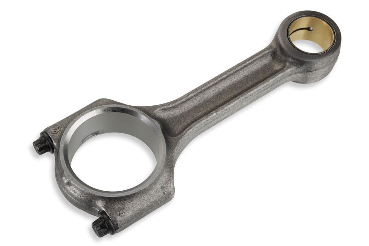
Among the basic components of an Internal Combustion engine, the Connecting Rod for IC Engine is the most important and critical. The connecting rod is subjected to alternating direct compressive and tensile forces. Since the compressive forces are much higher than the tensile forces, therefore the cross-section of the connecting rod is designed as a strut and Rankine’s formula is used. In this article, we will understand the design of Connecting Rod for an IC Engine.

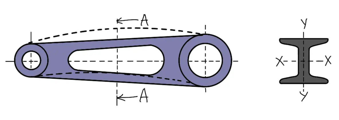
A connecting rod subjected to an axial load W may buckle with the X-axis as the neutral axis (i.e. in the plane of motion of the connecting rod) or the Y-axis as the neutral axis (i.e. in the plane perpendicular to the plane of motion).
The connecting rod is considered like both ends hinged for buckling about X-axis and both ends fixed for buckling about Y-axis. A connecting rod should be equally strong in buckling about either axes.
Let
A = Cross-sectional area of the connecting rod
l = Length of the connecting rod,
σc = Compressive yield stress
Wcr = Crippling or buckling load,
Ixx and Iyy = Moment of inertia of the section about the X-axis and Y-axis respectively,
kxx and kyy = Radius of gyration of the section about the X-axis and Y-axis respectively.
According to Rankine’s formula,
Wcr about X-axis

Wcr about Y-axis

In order to have a connecting rod equally strong in buckling about both axes, the buckling loads must be equal, i.e.
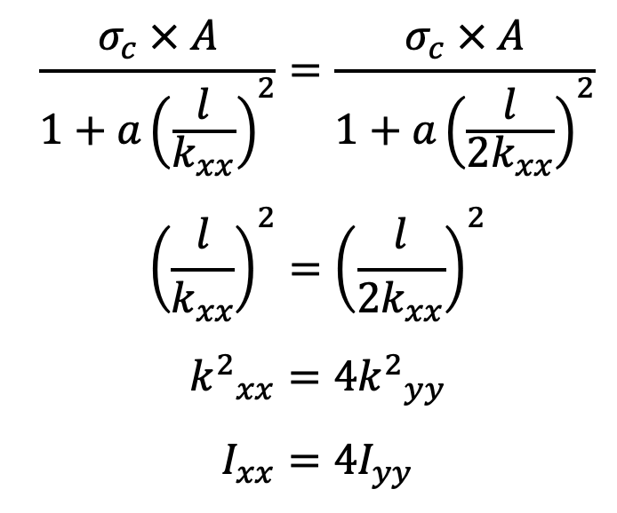
This shows that the connecting rod is four times strong in buckling about Y-axis than about X-axis.
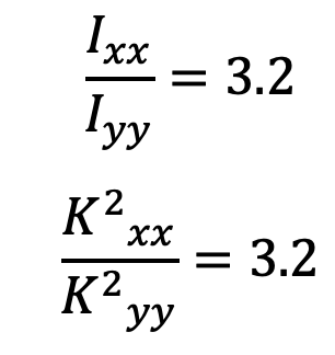
If Ixx > 4 Iyy, then buckling will occur about Y-axis, and if Ixx < 4 Iyy, buckling will occur about X-axis. In actual practice, Ixx is kept slightly less than 4 Iyy.
It is usually taken between 3 and 3.5 and the connecting rod is designed for buckling about X-axis. The design will always be satisfactory for buckling about Y-axis.
The most suitable section for the connecting rod is the I-section with the proportions as shown in the following figure.
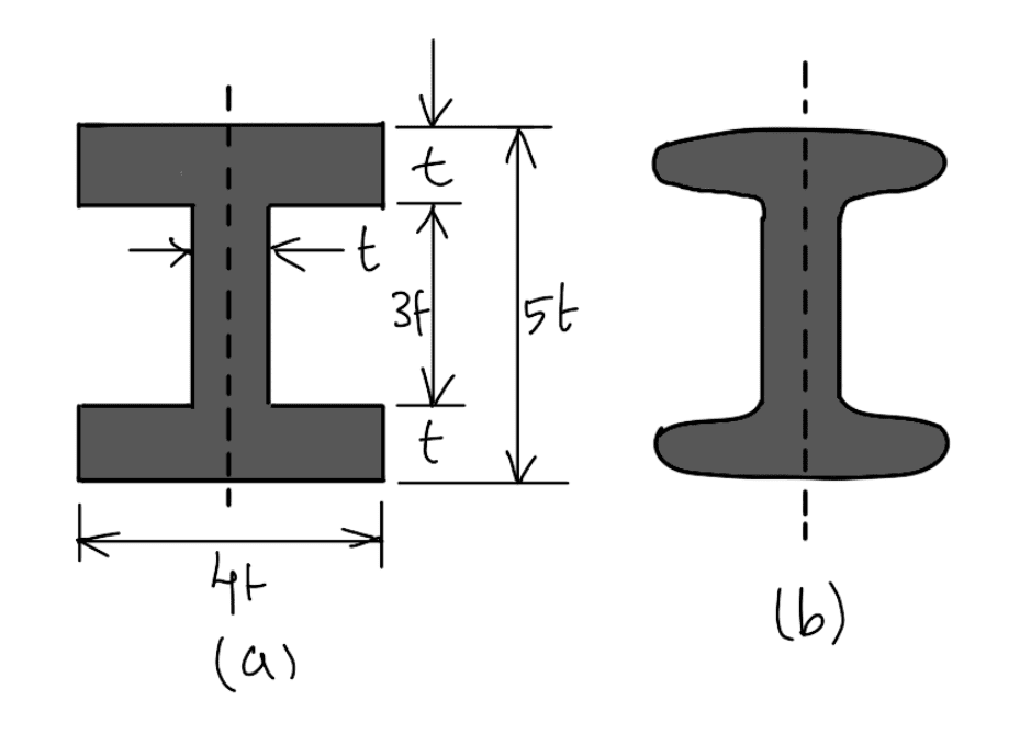
Area of the section = 2 (4 t × t) + 3 t × t = 11 t2
Moment of inertia about the X-axis,

and moment of inertia about the Y-axis,

Now, Ixx/Iyy

Since the value of Ixx/Iyy lies between 3 and 3.5, therefore I-section chosen is quite satisfactory.
Notes:
- The I-section of the connecting rod is used due to its lightness and to keep the inertia forces as low as possible. It can also withstand high gas pressure.
- Sometimes a connecting rod may have a rectangular section. For slow-speed engines, circular sections may be used.
- Since the connecting rod is manufactured by forging, therefore the sharp corners of the I-section are rounded off as shown in the above figure for easy removal of the section from the dies.
Design of Connecting Rod
Problem Statement: A connecting rod of length l may be considered as a strut with the ends free to turn on the crank pin and the gudgeon pin. In the directions of the axes of these pins, however, it may be considered as having fixed ends. Assuming that Euler’s formula is applicable, determine the ratio of the sides of the rectangular cross-section so that the connecting rod is equally strong in both planes of buckling.
Answer:
The rectangular cross-section of the connecting rod is shown in the following figure.
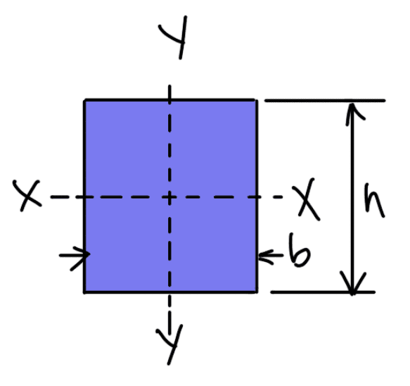
Let,
b = Width of rectangular cross-section,
h = Depth of rectangular cross-section.
Moment of inertia about X-X,
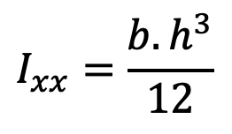
and moment of inertia about Y-Y,
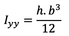
According to Euler’s formula, buckling load,
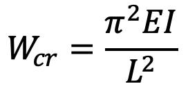
Buckling load about X-X,
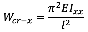
and buckling load about Y-Y,

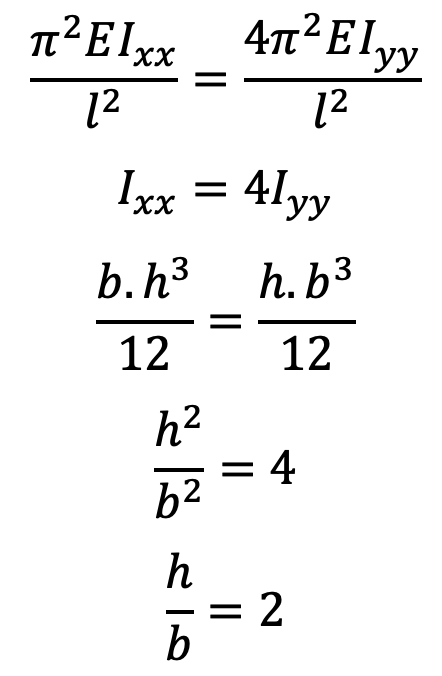
In order to have the connecting rod equally strong in both the planes of buckling,
Wcr (X-axis) = Wcr (Y-axis)
Example problem to design a Connection Rod I-section
Problem Statement: Determine the dimensions of an I-section connecting rod for a petrol engine from the following data and the relations from the different Forces Acting on a Connecting Rod:
Diameter of the piston = 110 mm
Mass of the reciprocating parts = 2 kg
Length of the connecting rod from center to center = 325 mm
Stroke length = 150mm
Speed in R.P.M. = 1500 with a possible Overspeed of 2500
Compression ratio = 4: 1
Maximum explosion pressure = 2.5 N/mm2
Answer:
We know that the radius of the crank, r = Stroke length /2 150 / 2 = 75mm = 0.075m
The ratio of the length of connecting rod to the radius of the crank n = l/r = 325/75 = 4.3
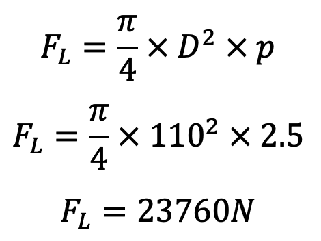
We know that the maximum force on the piston due to pressure,
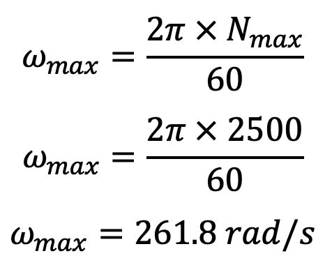
The maximum angular speed from the previous article,
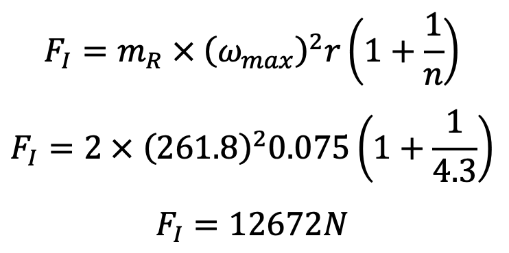
We know that the maximum inertia force of reciprocating parts from the previous article,

The inertia force of reciprocating parts is maximum when the crank is at the inner dead center, i.e. when θ = 0°
Since the connecting rod is designed by taking the force in the connecting rod (FC) equal to the maximum force on the piston due to gas pressure (FL), therefore
Force in the connecting rod, FC = FL = 23760N
Consider the I-section of the connecting rod with the proportions as shown in the following figure.

We have also discussed that the connecting rod is designed for buckling about the X-axis (i.e. in a plane of motion of the connecting rod), assuming both ends are hinged. Taking a factor of safety as 6, the buckling load,
Wcr = FC × 6 = 23760 × 6 = 142560N
and area of cross-section, A = 2 (4t × t) + t × 3t = 11 t2 mm2
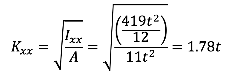
Moment of inertia about the X-axis,

The radius of gyration,
We know that the equivalent length of the rod for both ends is hinged, L = l = 325mm
Taking for mild steel, σc = 320 MPa = 320 N/mm2 and a = 1 / 7500, we have from Rankine’s formula,
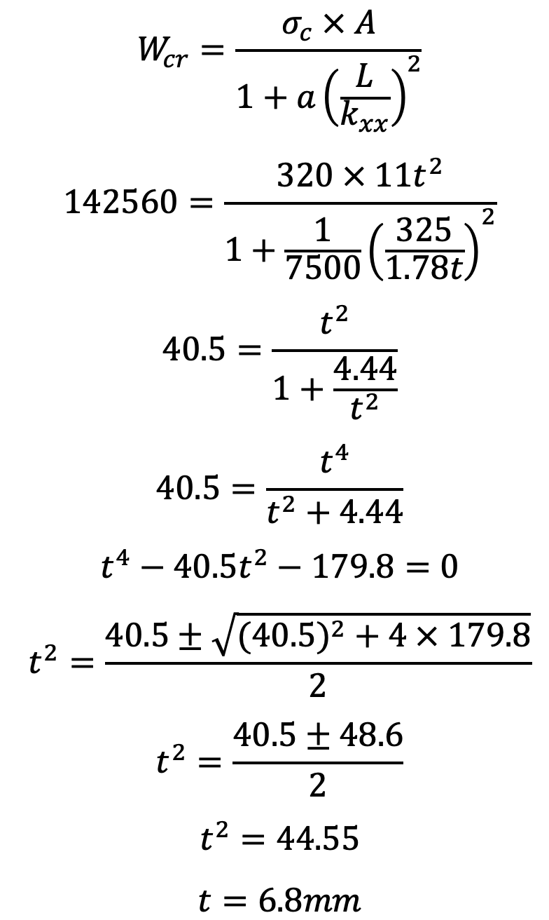
Therefore, the dimensions of the cross-section of the connecting rod are
Height = 5t = 5 × 6.8 = 34mm
Width = 4t = 4 × 6.8 = 27.2mm
The thickness of flange and web = t = 6.8mm = 0.0068m
From these parameters, we can design the Connecting Rod for IC Engine. Let us know what you think about this article in the comment section below.

Leave a Reply