A composite shaft is a shaft made up of two different diameters. The composite shaft may experience twist when they subjected to the torque. This twist can be obtained in these composite shaft, be based on the torque applied position when the shafts in series and parallel.

A composite shaft
When a shaft is having two different diameters sections it said as the composite shaft and it is subjected to torque at the different planes, then the angle of twist in the shaft is to be calculated by considering them in either series or parallel.
But how we can say the shafts are in series or parallel?
It is not something like series connection or parallel connection of circuits in the electrical subject. This is way different than it. Let’s see each of them in detail.
Torsion of shafts in Series
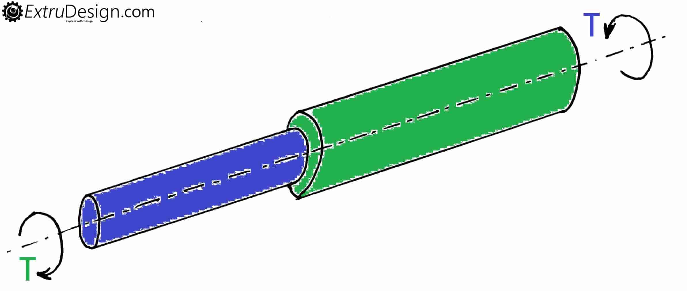
When a shaft is having two different diameters cross section then two equal torques (T) are applied in opposite direction at both ends as shown in the figure. Then the shafts are said to be in series.
Otherwise, one end is fixed and the other end is subjected to a torque T, then also the shafts are said to be in series.
When two shafts are in series then the angle of twist in the composite shaft is θ = θ1 + θ2
And this composite shaft(Series) transmit same torque throughout the shaft. i.e. T
We know the torsion equation
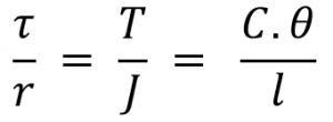
Where
τ = Torsional stress induced at the outer surface of the shaft (Maximum Shear stress)
r = Radius of the shaft
T = Twisting Moment or Torque
J = Polar moment of inertia
C = Modulus of rigidity for the shaft material.
l = Length of the shaft
θ = Angle of twist in radians on a length
From this equation consider
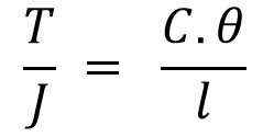
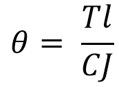
from the above equation, we can write the total angle of the twist as

Where c is the Modulus of rigidity for the shaft material, so if the shaft is made up of the same material, then C1 = C2 = C
We can write the above equation as follows

Torsion of shafts in Parallel
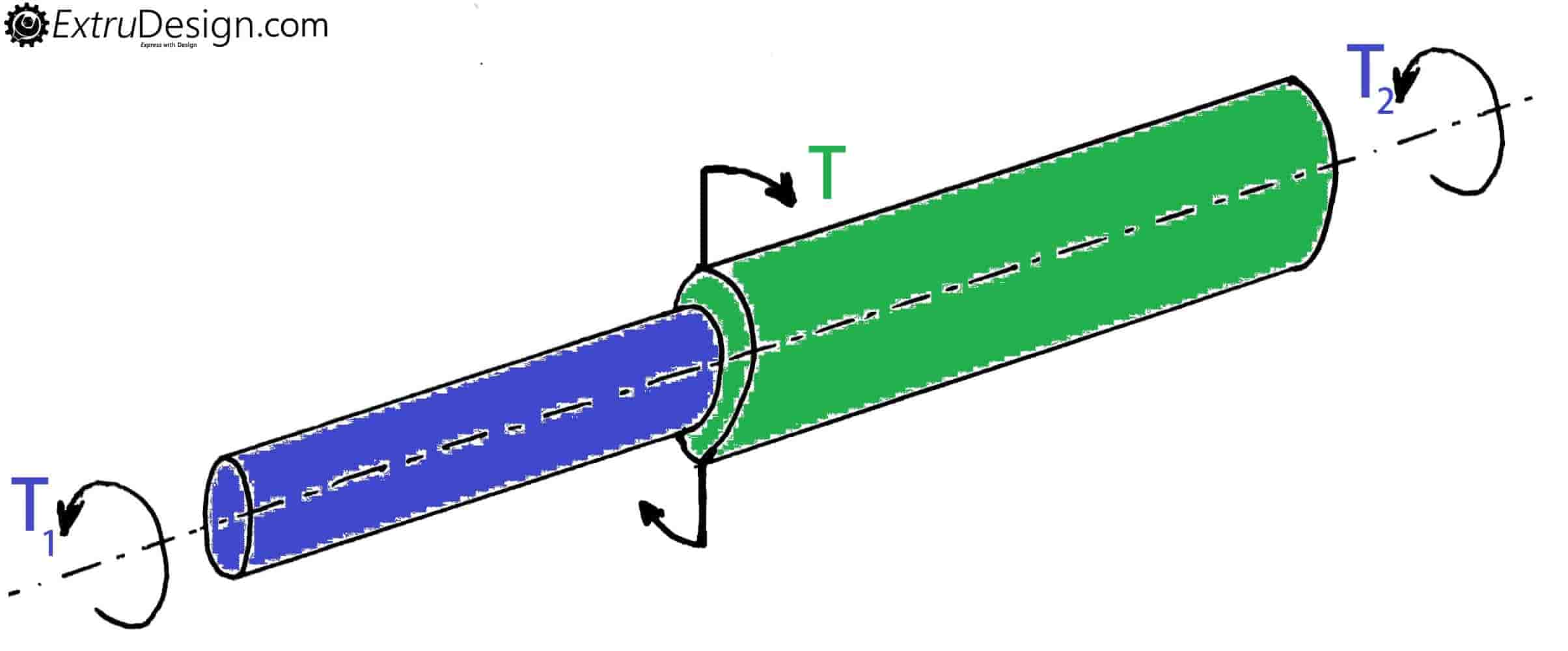
When a shaft is having two different diameters cross section then a torque (T) is applied at the centre (Junction of the two different section) and two opposite torques T1 and T2 as shown in the figure. Then the shafts are said to be in parallel.
Otherwise, the two ends are fixed and at the junction should be subjected to a torque T, then also the shafts are said to be in parallel.
When shafts are in parallel then the angle of twist in the composite shaft is θ1 = θ2
And the total torque transmitted thru the composite shaft (Parallel) T = T1 + T2
From the torsion equation, we can write total twist is θ1 = θ2 as follows
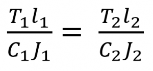
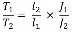
Where c is the Modulus of rigidity for the shaft material, so if the shaft is made up of the same material, then
C1 = C2 = C
Conclusion
This topic Shafts in series and parallel are use full when we design composite shafts and mount so many gears on one shaft that time this concept will come into the picture.

Dear sir,
Can you please tell me the easiest way to derive the torsion equation.
Simple? Yes sure, every deriving procedure looks similar approach. But I can help you with a video tutorial from the internet my friend.
**(Video Link Unfortunately removed)
And also check this post with is really helpful for your needs and understanding of the Torsion equation derivation.
https://extrudesign.com/torsional-stress-torsional-shear-stress/
It’s good but What about equivalent spring constant in series and parallel composite shafts ? It is confusing with this.
Check this article: https://extrudesign.com/bending-stress-in-curved-beams/
Very nicely explained…… Thank you so much sir
Welcome