Interferometry is nothing but optical interference to carry out precise measurements of very small linear dimensions. NPL Flatness Interferometer is developed by the National Physical Laboratory of the United Kingdom. We will discuss this NPL Flatness Interferometer construction and working principle with help of a schematic diagram.

Construction of NPL Flatness Interferometer
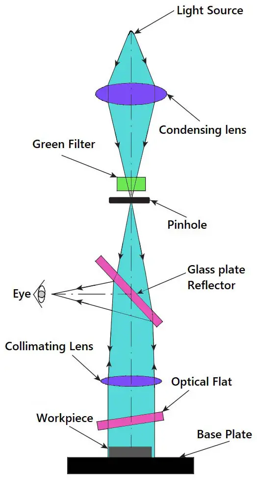
The NPL Flatness Interferometer comprises a simple optical system, which provides a sharp image of the fringes to allow the user to view them.

- The light from a mercury vapour lamp is condensed and passed through a green filter, resulting in a green monochromatic light source.
- The light will now pass through a pinhole, giving an intense point source of monochromatic light.
- The pinhole is positioned such that it is in the focal plane of a collimating lens.
- Therefore, the collimating lens projects a parallel beam of light onto the face of the gauge to be tested via an optical flat. This results in the formation of interference fringes.
- The light beam, which carries an image of the fringes, is reflected and directed by 90° using a glass plate reflector.
- The entire optical system is enclosed in a metal or fibreglass body.
- It is provided with adjustments to vary the angle of the optical flat, which is mounted on an adjustable tripod.
- In addition, the base plate is designed to be rotated so that the fringes can be oriented to the best advantage.
Working Principle of NPL Flatness Interferometer

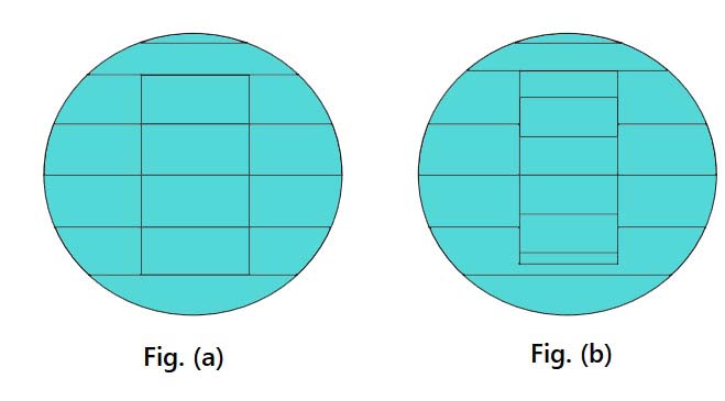
The Above Figure illustrates the fringe pattern that is typically observed on the gauge surface as well as the base plate.
- In Figure (a), the fringes are parallel and equal in number on the two surfaces.
- Obviously, the two surfaces are parallel, which means that the gauge surface is perfectly flat.
- On the other hand, in Figure (b), the number of fringes is unequal and, since the base plate surface is ensured to be perfectly flat, the workpiece surface has a flatness error.
- Due to the flatness error, the optical flat makes unequal angles with the workpiece and the base plate, resulting in an unequal number of fringes.
- Most of the times fringes will not be parallel lines but will curve out in a particular fashion depending on the extent of wear and tear of the upper surface of the workpiece.
- In such cases, the fringe pattern gives a clue about the nature and direction of wear.
Measuring Error in Parallelism with NPL Flatness Interferometer
The NPL flatness interferometer is used for checking flatness between gauge surfaces.
- The gauge to be checked is placed on a base plate that has a high degree of flatness.
- If the gauge length is smaller than 25mm, the gauge is placed on the base plate and the fringe pattern is observed.
- If the gauge being inspected is free from flatness error, then the fringes formed on both the gauge surface and the base plate are equally spaced.
- For gauges longer than 25mm, the fringe pattern on the base plate is difficult to observe.
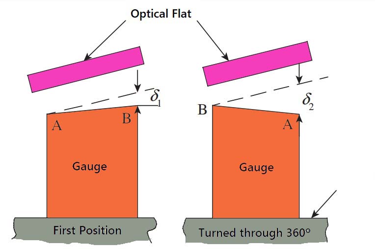
- Therefore, the gauge is placed on a rotary table, as shown below in Figure.
- Suppose the gauge surface has a flatness error, because of the angle it makes with the optical flat, a number of fringes are seen on the gauge surface.
- Now the table is rotated through 180°, and the surface of the gauge becomes even less parallel to the optical flat.
- This results in more fringes appearing on the gauge surface.

Let us consider a gauge that shows n1 fringes along with its length in the first position and n2 in the second position. As seen in the above Figure, the distance between the gauge and the optical flat in the first position has increased by a distance 𝛿1 over the length of the gauge, and in the second position by a distance 𝛿2. It is clear that the distance between the gauge and the optical flat changes by λ/2, between adjacent fringes.
Therefore, 𝛿1 = n1 × λ/2 and 𝛿2 = n2 × λ/2
The change in angular relationship is (𝛿2 − 𝛿1), that is, (𝛿2 − 𝛿1) = (n1− n2) × λ/2.
The error in parallelism is actually (𝛿2 − 𝛿1) /2 because of the doubling effect due to the rotation of the base plate.
Thus,
(𝛿2 − 𝛿1) /2 = (n1− n2)/2 × (λ/2)
Conclusion
We have discussed the NPL Flatness Interferometer with the construction, working principle and the measuring error in the parallelism of gauges. Let us know what do you think about this in the comment section below.

Leave a Reply