We have discussed what is a force in the previous article. let us discuss more details of force such as characteristics of Force, Representation of force, Classification of force, and Force System. Also, we will discuss how to draw the free-body diagrams and find the resultant force of a force system.

Force is something that changes or tends to change the state of rest or of uniform motion of a body in a straight line. Force is the direct or indirect action of one body on another. The bodies may be in direct contact with each other causing direct motion or separated by distance but subjected to gravitational effects.
There are different kinds of forces such as gravitational, frictional, magnetic, inertia or those caused by mass and acceleration. A static force is one that is caused without relative acceleration of the bodies in question.
The force has a magnitude and direction, therefore, it is a vector.
Characteristics Of A Force
The characteristics or elements of the force are the quantities by which a force is fully represented. These are:
- Magnitude (i.e., 50 N, 100 N,… etc.)
- Direction or line of action (angle relative to a coordinate system).
- Sense or nature (push or pull).
- Point of application
Representation Of Forces
Forces may be represented in the following two ways:
Vector representation: A force can be represented graphically by a vector as shown in the below figures.

A vector quantity is represented by a line carrying an arrowhead at one end. The length of the line (to a convenient scale) equals the magnitude of the vector. The line, together with its arrowhead, defines the direction of the vector. Suppose a force of 60 N is applied to point A in the above figure (Right) at an angle of 45° to the horizontal. The vector AB represents this force since its length equals 60 N (to scale) and its direction is proper. If the vector BA is drawn to the same scale as shown in the above figure (left) it represents a 60 N force having a direction exactly opposite to vector AB.
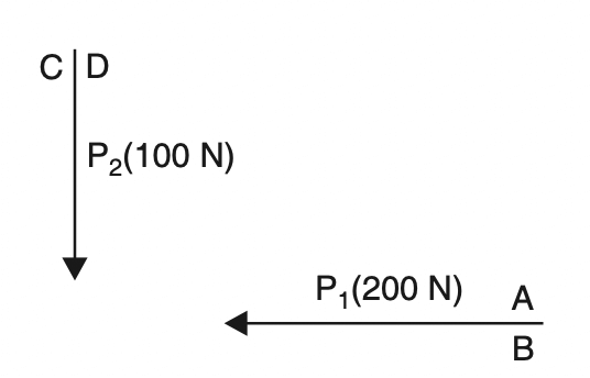
Bow’s Notation: It is a method of designating a force by writing two capital letters one on either side of the force shown in the below figure, where force P1 (200 N) is represented by AB and force P2 (100 N) by CD.
Classification Of Forces
There are several ways in which forces can be classified. Some of the important classifications of Forces are given as under :
1. According to the effect produced by the force :
(i) External force: When a force is applied externally to a body it is called external force.
(ii) Internal force: The resistance to deformation, or change of shape, exerted by the material of a body is called an internal force.
(iii) Active force: An active force is one that causes a body to move or change its shape.
(iv) Passive force: A force that prevents the motion and deformation of a body is called a passive
force.
2. According to the nature of the force
(i) Action and reaction: Whenever there are two bodies in contact, each exerts a force on
the other. Out of these forces, one is called action and the other is called reaction. Action and reaction are equal and opposite.
(ii) Attraction and repulsion:These are actually non-contacting forces exerted by one body or another without any visible medium transmission such as magnetic forces.
(iii) Tension and thrust: When a body is dragged with a string the force communicated to
the body by the string is called the tension while, if we push the body with a rod, the force exerted on the body is called a thrust.
3. According to whether the force acts at a point or is distributed over a large area.
(i) Concentrated force: The force whose point of application is so small that it may be considered as a point is called a concentrated force.
(ii) Distributed force: A distributed force is one whose place of application is area.
4. According to whether the force acts at a distance or by contact.
(i) Non-contacting forces or forces at a distance: Magnetic, electrical and gravitational forces are examples of non-contacting forces or forces at a distance.
(ii) Contacting forces or forces by contact: The pressure of steam in a cylinder and that of the wheels of a locomotive on the supporting rails are examples of contact forces.
Force Systems
A force system is a collection of forces acting on a body in one or more planes.
According to the relative positions of the lines of action of the forces, the forces may be classified
as follows :
- Coplanar concurrent collinear force system: It is the simplest force system and includes those forces whose vectors lie along the same straight line (as shown in the below figure).

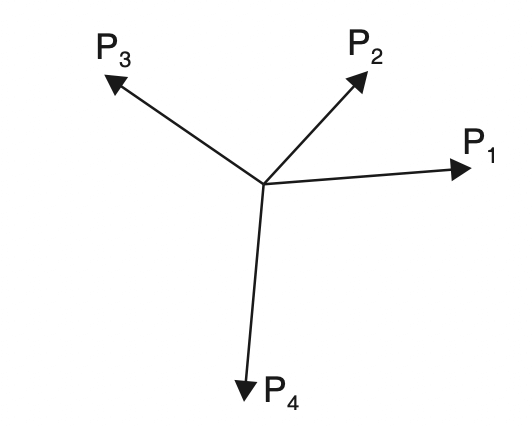
- Coplanar concurrent non-parallel force system: Forces whose lines of action pass through a common point are called concurrent forces. In this system lines of action of all the forces meet at a point but have different directions in the same plane as shown in the below figure.
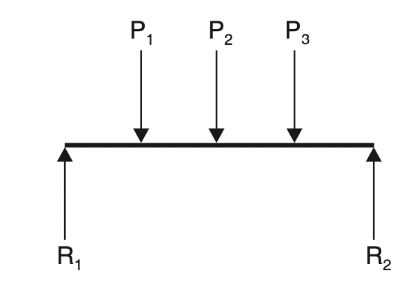
- Coplanar non-concurrent parallel force system: In this system, the lines of action of all the forces lie in the same plane and are parallel to each other but may not have the same direction as shown in the below figure.
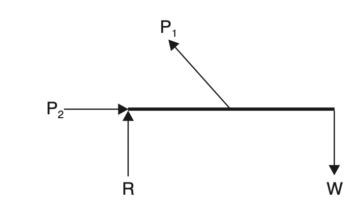
- Coplanar non-concurrent non-parallel force system: Such a system exists where the lines of action of all forces lie in the same plane but do not pass through a common point. Fig. 2.5 shows such a force system.
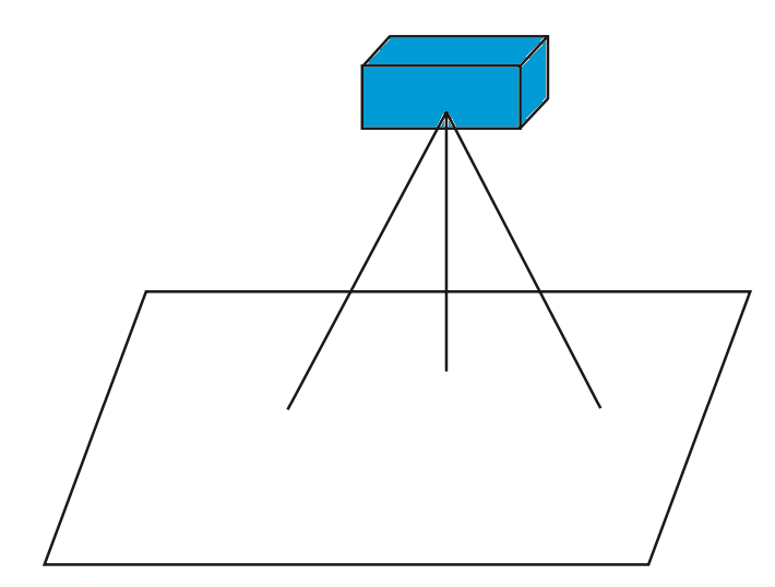
- Non-coplanar concurrent force system: This system is evident where the lines of action of all forces do not lie in the same plane but do pass through a common point. An example of this force system is the forces in the legs of the tripod support for the camera as shown in the below figure.
- non-coplanar non-concurrent force system: Where the lines of action of all forces do not lie in the same plane and do not pass through a common point, a non-coplanar non-concurrent system is present.
Free Body Diagrams for a Force System
A body may consist of more than one element and support. Each element or support can be isolated from the rest of the system by incorporating the net effect of the remaining system through a set of forces. This diagram of the isolated element or a portion of the body along with the net effects of the system on it is called a ‘free-body diagram’. Free-body diagrams are useful in solving the forces and deformations of the system.
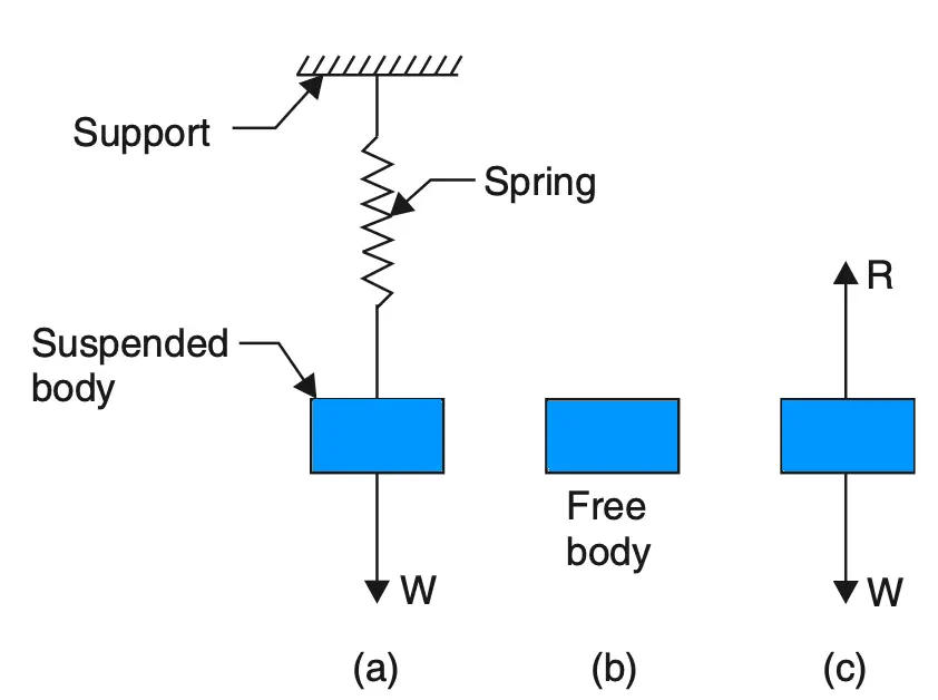
In the case of a body, as shown in the above figure, we remove the supporting springs and replace them with the reactive force R equal to W in magnitude. Figure (c) in which the body is completely isolated from its support and in which all forces acting on it are shown by vectors is called a free body diagram.
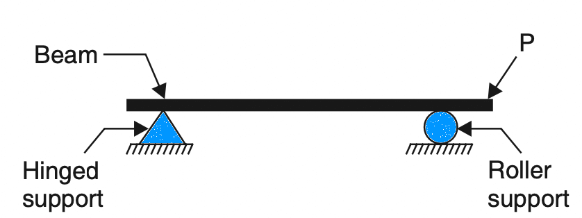
Let us consider another case of a beam as shown in the below figure. The beam is supported on a hinge at the left end and on a roller at the right end. The hinge offers vertical and horizontal reactions whereas the roller offers vertical reactions.
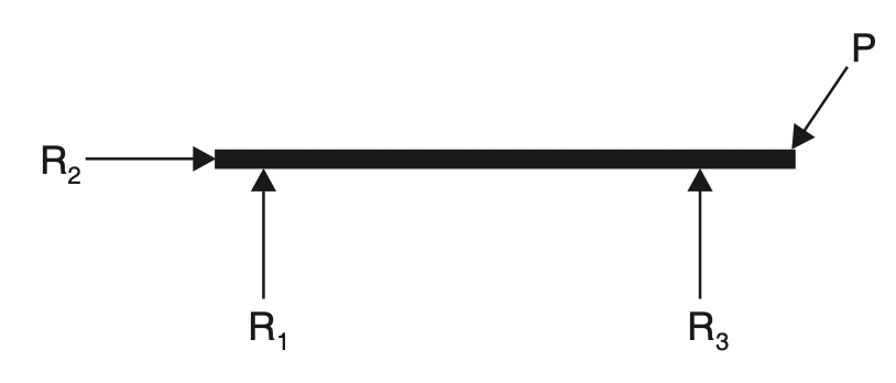
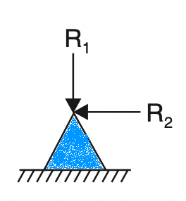
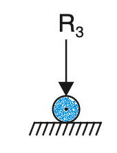
The beam can be isolated from the supports by setting equivalent forces of the supports. The below figure illustrates the free body diagram of the beam in which R1 and R2 are reactions of the hinge support and R3 the reaction of the roller support.
Similarly, the free-body diagrams of the hinge (a) and roller (b) supports are represented below respectively.
Transmissibility of Force
The principle of transmissibility of forces states that when a force acts upon a body, its effect is the same whatever point in its line of action is taken as the point of the application provided that the point is connected with the rest of the body in the same invariable manner.
A force may be considered as acting at any point in its line of action so long as the direction and magnitude are not changed.
Suppose a body as shown in the below is to be moved by a horizontal force P applied by hooking a rope to some point on the body.
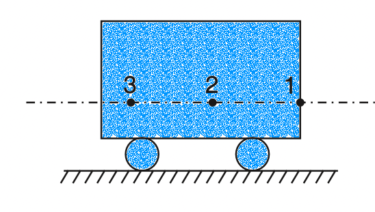
The force P will have the same effect if it is applied at 1, 2, 3 as shown in the below figure or at any point in its line of action. This property of force is called transmissibility.

Important Definitions
Particle: A body whose dimensions are practically negligible is called a particle. In any problem of mechanics, when the applied forces have no tendency to rotate the body on which they act, the body may be considered a particle. Forces acting on the particle are concurrent, the point through which they pass is the point representing the particle.
Resultant Force: A resultant force is a single force that can replace two or more forces and produce the same effect on the body as the forces. It is a fundamental principle of mechanics, demonstrated by experiment, that when a force acts on a body that is free to move, the motion of the body is in the direction of the force, and the distance travelled in a unit of time depends on the magnitude of the force. Then, for a system of concurrent forces acting on a body, the body will move in the direction of the resultant of that system, and the distance travelled in a unit of time will depend on the magnitude of the resultant.
Component Of A Force
As two forces acting simultaneously on a particle acting along directions inclined to each other can be replaced by a single force that produces the same effect as the given force, similarly, a single force can be replaced by two forces acting in directions that will produce the same effect as the given force. This breaking up of a force into two parts is called the resolution of a force. The force which is broken into two parts is called the resolved force and the parts are called component forces or the resolutes.
Generally, a force is resolved into the following two types of components :
- Mutually perpendicular components
- Non-perpendicular components.
1. Mutually perpendicular components
Let the force P be resolved is represented in magnitude and direction by oc in the below figure.
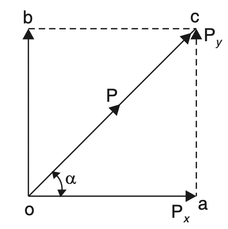
Let Px be the component of force P in the direction oa making an angle α with the direction oc of the force. Complete the rectangle oabc.
Then the other component Py at a right angle to Px will be represented by ob which is also equal to ac.
From the right-angled triangle oac
Px = oa = P cos α
Py = ac = P sin α.
2. Non-perpendicular components
Refer to the following figure Let oc represents the given force P in magnitude and direction to some scale.
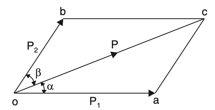
Draw oa and ob making angles α and β with oc. Through c draw ca parallel to ob and cb parallel to oa to complete the parallelogram oacb.
Then the vectors oa and ob represent in magnitude and direction (to the same scale) the components P1 and P2 respectively.
Now from the triangle oac, by applying the sine rule,
oa / (sinβ) = oc / (sin[180-(α+β)]) = ac / sinα
P1 / (sinβ) = P/ sin(α+β) = P2 / sinα
P1 = P . sinβ / sin (α+β) … Equation [1]
P2 = P . sinα / sin (α+β) … Equation [2]
Principle Of Resolved Parts
The principle of resolved parts states: “The sum of the resolved parts of two forces acting at a point in any given direction is equal to the resolved parts of their resultant in that direction.
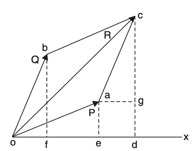
Referring to the above figure, Let the two forces P and Q be represented by the sides oa and ob of the parallelogram oacb and The resultant R of these two forces is given by the diagonal oc in magnitude and direction. Let ox is the given direction. Draw bf, ae, cd and ag perpendicular to cd.
Now from the two triangles obf and acg which are the same in all respects, we get
of = ag = ed
od = oe + ed = oe + of
But oe, of and od represent the resolved components or parts of the forces P, Q and R respectively in the direction of ox.
It may be noted that this principle holds good for any number of forces.
Laws Of Forces
The method of determination of the resultant of some forces acting simultaneously on a particle is called the composition of forces. The various laws used for the composition of forces are given as under :
- Parallelogram law of forces
- Triangle law of forces
- Polygon law of forces
1. Parallelogram law of forces
It states as under “If two forces, acting simultaneously on a particle, be represented in magnitude and direction by the two adjacent sides of a parallelogram then their resultant may be represented in magnitude and direction by the diagonal of the parallelogram which passes through their point of intersection.”
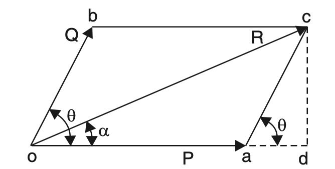
Refer above figure. Let two forces P and Q acting simultaneously on a particle be represented in magnitude and direction by the adjacent sides oa and ob of a parallelogram oacb drawn from a point o, their resultant R will be represented in magnitude and direction by the diagonal oc of the parallelogram.
The value of R can be determined either graphically or analytically as explained below:
Graphical method
Draw vectors oa and ob to represent to some convenient scale the forces P and Q in magnitude and direction. Complete the parallelogram oacb by drawing ac parallel to ob and bc parallel to oa.
The vector oc measured to the same scale will represent the resultant force R.
Analytical method
As shown in the above figure, in the parallelogram oacb, from c drop a perpendicular cd to oa at d when produced. Now from the geometry of the figure.
∠cad = θ
ac = Q
cd = Q sin θ
ad = Q cos θ
From right-angled triangle, odc
oc = √[(od)2 (cd)2]
oc= √[(oa+ad)2+(cd)2]
R = √[(P+Q cosθ)2 +( Q sin θ )2 ]
R = √[P2 +Q2 cos2 θ+ 2PQ cosθ +Q2 sin2θ]
R = √[P2 Q2 (sin2θ + cos2θ)+ 2PQ cosθ]
R = √[P2 +Q2 +2PQ cosθ] (∵ sin2 θ + cos2 θ = 1)
R =√[P2 +Q2 + 2PQ cosθ ] … Equation [3]
Let the resultant makes an angle α with P as shown in the figure.
Then tan α = cd/od = cd/(oa+ad)
tan α = Q sin θ/P+Q cosθ … Equation [4]
Case 1 If θ = 0°, i.e., when the forces P and Q act along the same straight line then equation [3] reduces to
R = P + Q (∵ cos 0° = 1)
Case 2. If θ = 90°, i.e., when the forces P and Q act at right angles to each other, then
R = √[P2 +Q2 ] (∵ cos 90° = 0)
Case 3. If θ = 180°, i.e., the forces P and Q act along the same straight line but in opposite
directions, then
R = P – Q (∵ cos 180° = – 1)
The resultant will act in the direction of the greater force.
2. Triangle law of forces
It states: “If two forces acting simultaneously on a body are represented in magnitude and direction by the two sides of a triangle taken in order then their resultant may be represented in magnitude and direction by the third side taken in the opposite order.”
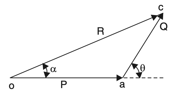
Let P and Q be the two coplanar concurrent forces. The resultant force R, in this case, can be obtained with the help of the triangle law of forces both graphically and analytically as given below :
Graphical method
Draw vectors oa and ac to represent the forces P and Q to some convenient scale in magnitude and direction. Join oc which will represent the resultant force R in magnitude and direction to the same scale.
Analytical method
From the geometry of triangle oac from above figure.
∠coa = α
∠oca = θ – α
∠cao = 180° – θ
oa/sin( θ-α ) = ac / sinα = oc/sin(180° – θ)
P/sin ( θ-α )= Q/ sin α = R/sin (180° – θ)
P/sin( θ-α ) = Q/sin α = R/sin θ … Equation [5]
3. Polygon Law of Forces
It states: “If a number of coplanar concurrent forces, acting simultaneously on a body are represented in magnitude and direction by the sides of a polygon taken in order, then their results may be represented in magnitude and direction by the closing side of a polygon, taken in the opposite order”.
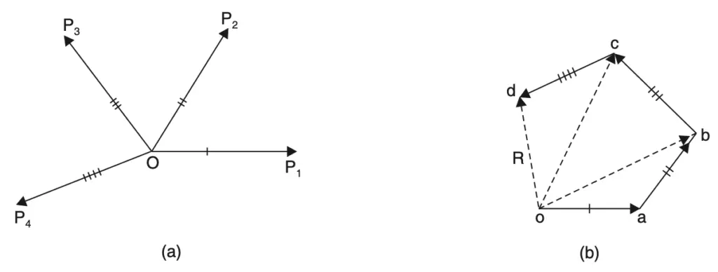
If the forces P1, P2, P3, and P4 acting simultaneously on a particle be represented in magnitude and direction by the sides oa, ab, bc and cd of a polygon respectively, their resultant is represented by the closing side do in the opposite direction as shown in the above figure.
The law is actually an extension of the triangle law of forces. This is so because ob is the resultant of oa and ab and therefore oc which is the resultant of ob and bc is also the resultant of oa, ab and bc.
Similarly, od is the resultant of oc and cd and therefore of ob, bc and cd and finally of oa, ab, bc and cd.
Resultant of Several Coplanar Concurrent Forces
To determine the resultant of a number of coplanar concurrent forces any of the following two methods may be used :
- Graphical method (Polygon law of forces)
- Analytical method (Principle of resolved parts)
Resultant by Graphical Method
The following figure shows the forces P1, P2 and P3 simultaneously acting at a particle O.
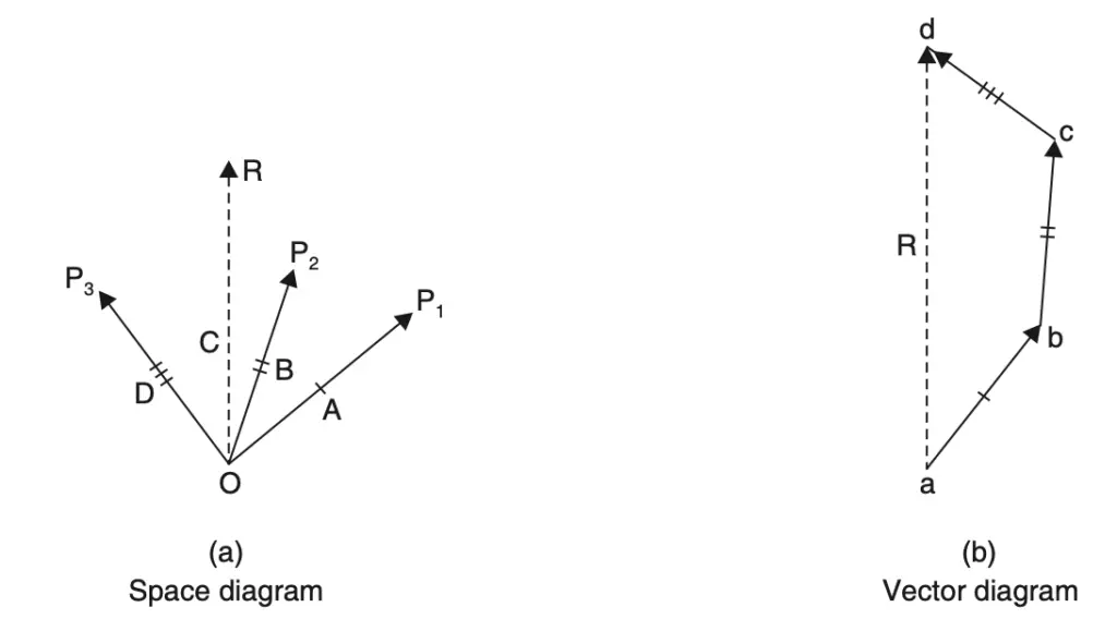
Draw a vector ab equal to force P1 to some suitable scale and parallel to the line of action of P1.
From ‘b’ draw vector bc to represent force P3 in magnitude and direction.
Now from ‘c’ draw vector cd equal and parallel to force P3.
Join ad which gives the required resultant in magnitude and direction, the direction being a to d as shown in the vector diagram.
Resultant by Analytical Method
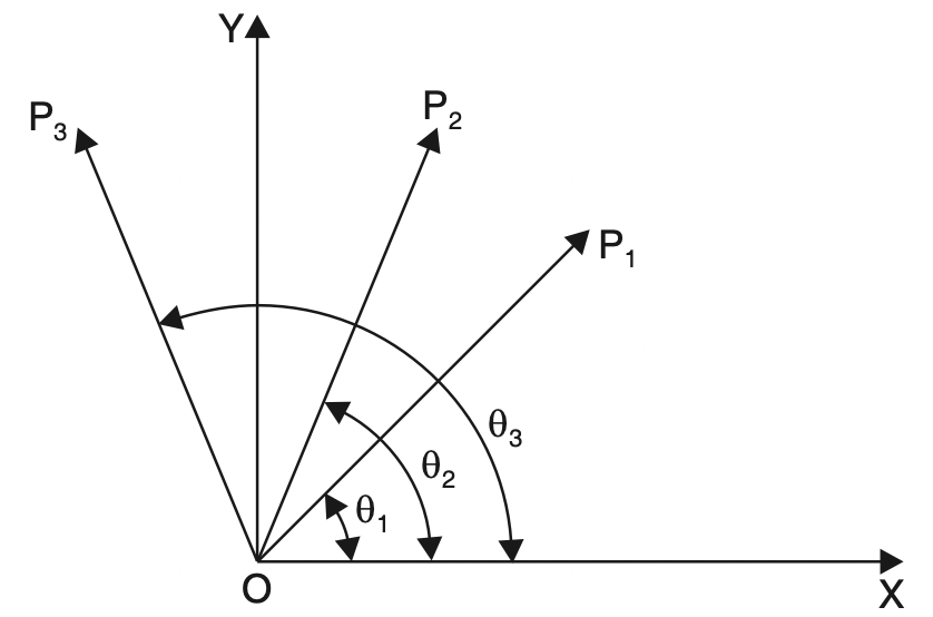
The resolved parts in the direction OX and OY of
P1 are P1 cos θ1 and P1 sin θ1, respectively,
P2 are P2 cos θ2 and P2 sin θ2 respectively
P3 and P3 cos θ3 and P3 sin θ3 respectively.
If the resultant R makes an angle θ with OX then by the principle of resolved parts :
R cos θ = P1 cos θ1 + P2 cos θ2 + P3 cos θ3
R cos θ = ΣH … Equation [6]
R sin θ = P1 sin θ1 + P2 sin θ2 + P3 sin θ3
sin θ = ΣV … Equation [7]
It may be noted that while solving problems proper care must be taken about the signs (+ve or –ve) of the resolved parts.
Following sign conventions may be kept in view :
Vertical components
Upward direction ↑ Positive (+)
Downward direction ↓ Negative (–)
Horizontal components
From left to right → Positive (+)
Directions :
From right to left ← Negative (–)
Let us solve Some example problems to find the resultant force magnitude and direction.
Example Problems to find Resultant Force
Example Problem 1: Find the magnitude and direction of the resultant of two forces 40 N and 60 N acting at a point with an included angle of 40° between them. The force of 60 N is horizontal.
Answer:
Refer to same figure we have drawn by graphical method for Parallelogram law of forces.

P = 60 N,
Q = 40 N,
θ = 40°
Using the Equation [3]
R = √[P2 +Q2 +2PQ cos θ]
R =√ [(60)2 +(40)2+ (2×60×40×cos 40°)]
R = √[3600 +1600+ (4800× 0.766)]
R = 94.22 N.
Hence magnitude of the resultant force = 94.22 N
Using the Equation [4]
tan α = Q sinθ / [P+Q cosθ]
tan α = 40 sin 40°/[60+40 cos 40°]
tan α = 25.71/[60+30.64]
tan α = 0.284
α = 15.85° or 15° 51′
Hence the direction of the resultant force 15° 51′ with the 60 N force.
Example Problem 2: The angle between the two forces of magnitude 20 N and 15 N is 60°; the 20 N force is horizontal. Determine the resultant in magnitude and direction, if
(a) the forces are pulls;
(b) the 15 N force is a push and the 20 N force is a pull.
Answer:
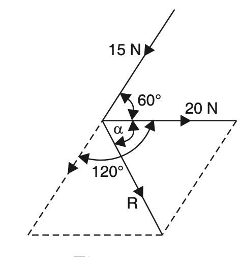
Case (a)
P = 20 N,
Q = 15 N,
θ = 60°
Using the Equation [3],
R = √[P2 +Q2 +2PQ cos θ]
R =√ [(20)2 +(15)2+ (2×20×15×cos 60°)]
R = √[400 + 225 + (600× 0. 5)]
R = 30.4 N.
Using the Equation [4]
tan α = Q sinθ / (P+Q cosθ)
tan α = (15 × sin 60°) / (20 + 15 cos 60°)
tanα = 12.99 /20+7.5
α = tan–1 [12.99/20+7.5]
α = 32.05° = 25° 3′
the direction of the resultant force 25° 3′ with 20N force
Case (b)
R = √[(20)2+(15)2+ (2× 20 ×15 cos 120°)]
R = √[400+225-300]
R = 18 N
tan α = 15 sin 120° / 20+ 15cos 120°
tan α = 12.99/(20-15× 0. 5)
tan α = 1.039
α = tan–1 (1.039)
α = 46.1° or 46° 6′ with 20 N force. (Ans.)
Example Problem 3: The resultant of two forces P and 30 N is 40 N inclined at 60° to the 30 N force. Find the magnitude and direction of P.
Answer:
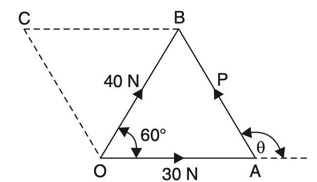
From the knowledge of trigonometry, we know that in ∆OAB,
AB2 = OA2 + OB2 – 2.OA . OB cos 60°
P2 = (30)2 + (40)2 – 2 × 30 × 40 cos 60°
P = √[900+ 1600- (2400×0 5)]
P = 36.06 N
Now applying the sine rule,
P/sin60° = 40/sin(180-θ)
36.06/0.866 = 40/sin(180-θ)
sin (180° – θ) = 40×0. 866/36.06
sin (180° – θ) = 0.96
180 – θ = 73.74° or 73° 44′
θ = 106° 16′
Conclusion
We have discussed the different systems of Forces with the free body diagrams and how to find the resultant forces. We have solved some Example Problems to find Resultant Force. Let us know what you think about this topic in the comment section below.

Leave a Reply