Have you ever wondered how to design a Hydraulic Press?? We use Hydraulic Press for many applications from a manufacturing point of view to compacting. In this article, we will understand how to design a hydraulic press by finding out the necessary parameter such as the diameter of the ram, vertical columns, and Hydraulic cylinder pressure. We will discuss this by solving a simple problem on a Hydraulic Press.
In the previous article, we have discussed the Different types of stresses that are induced in cylinders due to internal fluid pressures, also we have discussed the stresses in the thick cylinder with help of Lame’s equation, from these equations only we are going to solve a problem on a Hydraulic press.
Following is the problem statement for the Hydraulic Press.
Problem: The hydraulic press, having a working pressure of water as 16 N/mm2 and exerting a force of 80 kN is required to press materials upto a maximum size of 800 mm × 800 mm and 800 mm high, the stroke length is 80 mm.
Design and draw the following parts of the press :
- Design of ram
- Cylinder
- Pillars
- Gland
Answer:
Given that the Hydraulic press will work under a pressure of P = 16 N/mm2
An exerting force F = 80 kN = 80×103 N
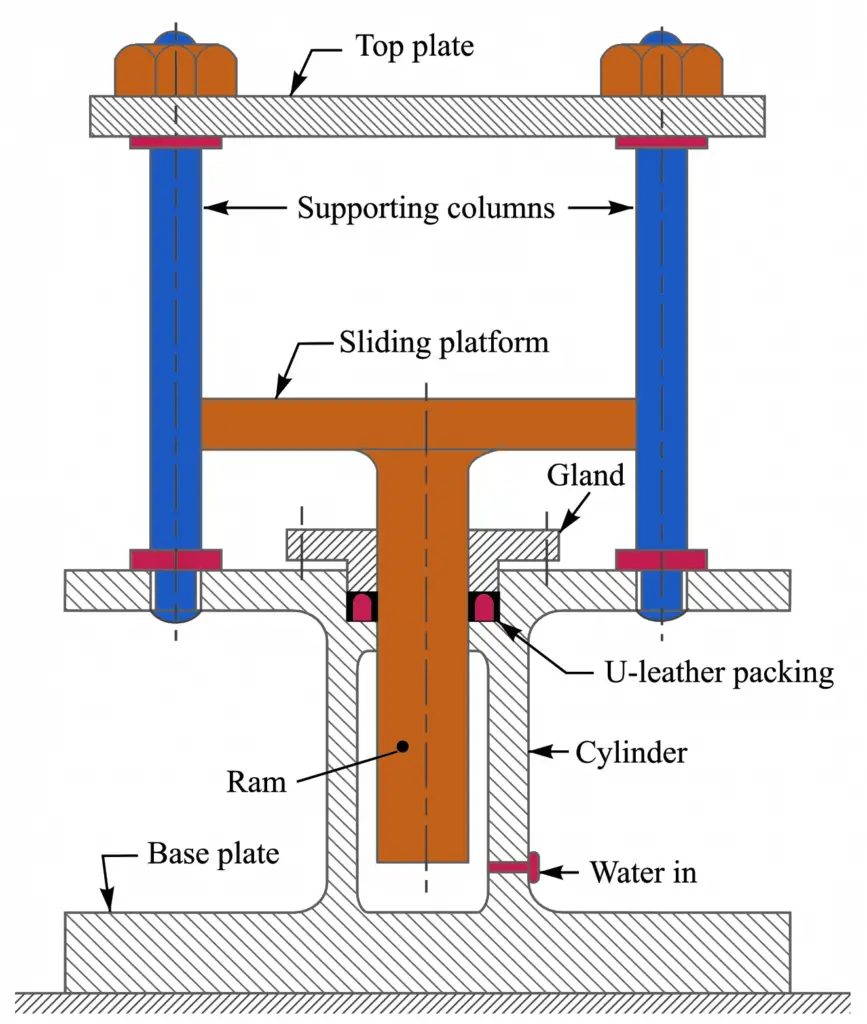
Following is the schematic representation of the Hydraulic press.
1. Design of Ram
Let us assume dr is the Diameter of the ram.
It is given that the maximum force to be exerted by the ram (F)
80 × 103 = π/4 (dr)2 P = π/4 (dr)2 16 = 12.57 (dr)2
(dr)2 = 80×103/12.57 = 6364
dr = 79.8
Let us say 80mm is the diameter of the Ram.
In case, the ram is made hollow to reduce its weight, then it can be designed as a thick cylinder subjected to external pressure. We have already discussed it in the previous article about the stresses in the thick cylinder, according to Lame’s equation,
The maximum tangential stress (considering external pressure only) is given as

And the maximum radial stress is given as
σr(max) = – po (compressive)
Where
dro = Outer diameter of ram = dr = 80 mm
dri = Inner diameter of ram
po = External pressure = p = 16 N/mm2 …(this values is given in the problem statement)
Now according to maximum shear stress theory for ductile materials, maximum shear stress is written as
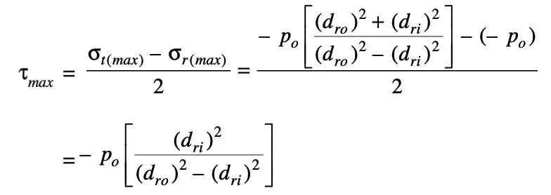
We know that the maximum shear stress is one-half the maximum principal stress (which is compressive), therefore

The ram is usually made of mild steel for which the compressive stress (σc)may be taken as 75 N/mm2. Substituting this value of stress in the above expression,
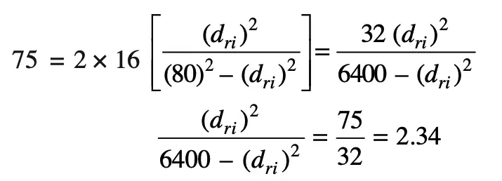
(dri)2 = = 2.34 [6400 – (dri)2] = 14 976 – 2.34 (dri)2
(dri)2 = 14 976/3.34 = 4484
dri = 67
we get the Inner diameter of the ram dri = 67mm
Also, we have calculated the outer diameter of the ram is dro = dr = 80 mm
2. Desgin of the Cylinder
Now let us design the Cylinder with the main design parameters of the Cylinder
dci = Inner diameter of cylinder
dco = Outer diameter of cylinder
Let us assume the clearance of 15 mm between the ram and the cylinder bore.
Therefore the inner diameter of the cylinder will be
dci = dro + Clearance (∴ dro = Outer diameter of the ram)
dci = 80+15 = 95
The Inner diameter of the cylinder is dci = 95 mm
The cylinder is usually made of cast iron for which the tensile stress may be taken as 30 N/mm2.
According to Lame’s equation, we know that wall thickness of a cylinder,

t = 47.5(1.81–1) = 38.5
Let us say 40mm
The cylinder is to be made up of 40mm thick.
Now we need to calculate the outer diameter of the Cylinder.
The outer diameter of the cylinder is dco = dci + 2t = 95 + 2×40 = 175mm
3. Design of Pillars
Let us assume the diameter of the pillar is dp
The main function of the pillars is to support the top plate and to guide the sliding plate.
When the material is being pressed, the pillars will be under direct tension.
Let us consider there are four pillars and the load is equally shared by these pillars.
∴ Load on each pillar = (80×103)/4 = 20×103 N ……. (i)
We know that load on each pillar = (π/4) (dp)2 σt
= (π/4) (dp)2 75
= 58.9 (dp)2 …… (ii)
From equations (i) and (ii),
58.9 (dp)2 = 20×103
(dp)2 = 20 × 103/58.9 = 340
dp = 18.4 mm
The Pillars diameter should be at least 18.4 mm to withstand the given loads in the problem statement.
From fine series of metric threads, let us adopt the threads on pillars as M20 × 1.5 having a major diameter of 20mm and core diameter of 18.16mm from the Design standard book.
4. Design of gland
Following is the schematic representation of the gland with the empirical parameters.
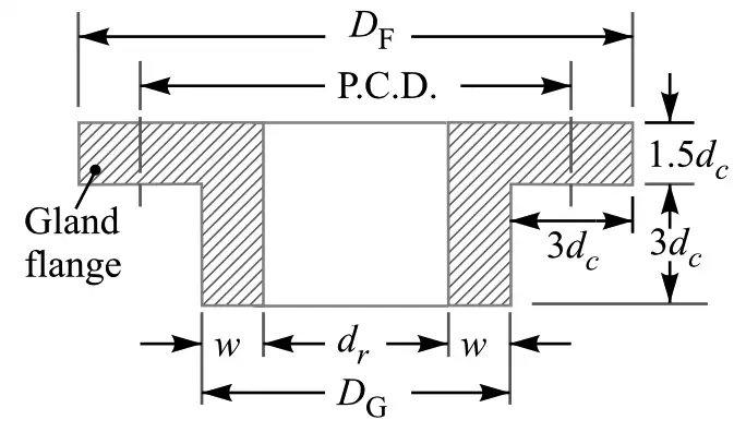
w = width of the U-leather packing
DG = Outer diameter of gland
DF = Outer diameter of the gland flange
P.C.D = Pitch circle diamter of the Gland
dc = core diameter of the stud
dr = Ram outer diameter = 80mm we already knew
The width (w) of the U-leather packing for a ram is given empirically as 2√dr to 2.5√dr.
Let us consider w = 2.2√dr = 2.2 √80 = 19.7
Let us say the width of the U-leather packing for the ram w is 20mm.
The outer diameter of the gland DG = dr +2w = 80+2×20 = 120mm
We know that the total upward load on the gland = Area of gland exposed to fluid pressure × Fluid pressure
= π (dr + w) w.p = π (80 + 20) 20 × 16 = 100 544 N
Let us assume that 8 studs equally spaced on the pitch circle of the gland flange are used for holding down the gland.
∴ Load on each stud = 100 544 / 8 = 12 568 N
If dc is the core diameter of the stud and σt is the permissible tensile stress for the stud material, then load on each stud will be
12 568 = (π/4) (dc)2 σt = (π/4) (dc)2 75 = 58.9 (dc)2
(dc)2 = 12568/58.9 = 213.4
dc =14.6mm
From fine series of metric threads, let us adopt the studs of size M18 × 1.5 having a major diameter of 18 mm and core diameter (dc) as 16.16 mm.
Pitch circle diameter of the gland flange (P.C.D) = DG +3dc =120+3×16.16 = 168.5mm
Outer diameter of the gland flange (DF) = DG +6dc =120+6×16.16 = 216.96 or 217mm
and the thickness of the gland flange = 1.5 dc = 1.5 × 16.16 = 24.24 or 24.5mm
With these parameters, we can design the Gland that supports the loads exerted by the ram by the given loads in the problem statement.
Conclusion
We have solved the sample problem on the hydraulic press and calculated the design parameters for the Ram, cylinder, Pillars, and the gland with the help of Lame’s equation which is used for the thick cylinders. Please let us know what do you think in the comment section below.

I found it interesting when you said that the main function of the pillars of a hydraulic press is to support the top plate and to guide the sliding plate. This must be helpful for metal forming industries that need to acquire custom hydraulic press machines. I could imagine how important it is to choose a hydraulic press manufacturer that offers custom-designed machines.
provide the calculation for top plate thickness