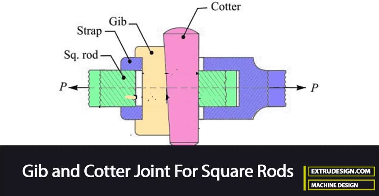
As you know, there are 3 different types of cotter joints. The Gib and Cotter Joint is one of them. The other two are the Socket and Spigot Cotter Joint, and Sleeve and cotter joint. In this article, we are going to discuss how to design the Gib and Cotter joint for Square rods to avoid possible failures in different parts of this cotter joint.

In the previous article, we have discussed the Gib and Cotter joint. Now let us directly go into the details of designing the Cotter joint for the square rods with a gib.
Design of Gib and Cotter Joint for Square Rods
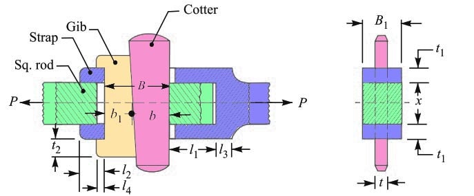
Consider a gib and cotter joint for square rods as shown below.

The rods may be subjected to a tensile or compressive load. All components of the joint are assumed to be of the same material.
Let us assume
P = Load carried by the rods,
x = Each side of the rod,
B = Total width of gib and cotter,
B1 = Width of the strap,
t = Thickness of cotter,
t1 = Thickness of the strap,
σt = Permissible tensile stress.
τ = Permissible shear stress,
σc = Permissible crushing stress.
In designing a gib and cotter joint to connect the square rods, the following modes of failure may occur. Or at least we need to consider these failures in order to determine the design parameters of the Gib and cotter joint to connect the Square rods.
- Failure of the rod in tension
- Failure of the gib and cotter in shearing
- Failure of the strap end in tension at the location of gib and cotter
- Failure of the strap or gib in crushing
- Failure of the rod end in shearing
- Failure of the strap end in shearing
1. Side width of the Rod (x)
The side of the rod can be obtained by considering the Failure in the square rod while it is in tension.
The rod may fail in tension due to the tensile load P. We already knew that the cross-section area that resists the tearing is = x × x = x2
The Tearing strength of the rod will be the product of the cross-sectional area of the rod and the induced tensile stress at that cross-section.
= x2 × σt
Let us equate this tearing strength to the load (P), we can write the relation as
P = x2 × σt
From this relation, we can determine the side width of the square rod (x).
The other dimensions are of the cotter joint for the square rod are fixed as follows.
Width of strap (B1) = Side of the square rod = x
The thickness of cotter (t) = 1/4 of the width of strap = B1/4
The thickness of gib = Thickness of cotter (t)
Height of the Gib head (t2) = Length of gib head (l4) = Thickness of cotter (t)
2. Width of the Gib and Cotter (B)
By considering the Failure of the gib and cotter in shearing, we can determine the Width of the Gib and Cotter.
As we have considered the Gib and cotter are in double shear, therefore,
The Area resisting failure = 2 B × t
The resisting strength = 2 B × t × τ
Equating this to the load (P), we have
P = 2B × t × τ
From this relation, we can determine the the width of gib and cotter (B).
In the above-shown cotter joint, one gib is used, the proportions of the parameters for the cotter joint with one gib are as follows.
Width of gib (b1) = 0.55 B
Width of cotter (b) = 0.45 B
If there are two gibs in the cotter joints, then the Width of each gib = 0.3 B; and width of cotter = 0.4 B
3. Thickness of the Strap (t1)
Let us consider the Failure of the strap end in tension at the location of the gib and cotter to obtain the thickness of the strap.
The Area resisting failure = 2 [B1× t1 – t1 × t]
= 2 [x × t1 – t1 × t] … ( we know B1 = x)
The Resisting strength = 2 [ x × t1 – t1 × t] σt
Equating this to the load (P), we have
P = 2 [x × t1 – t1 × t] σt
From this relation, we can determine the thickness of the strap (t1).
4. Induced Crushing Stress(σc)
In order to obtain the induced crushing stress, we need to assume that the strap or gib at the strap hole may fail due to crushing.
The Area resisting failure = 2 t1 × t
The Resisting strength = 2 t1 × t × σc
Equating this to the load (P), we have
P = 2 t1 × t × σc
From this equation, we can obtain the induced crushing stress (σc).
5. Length (l1) of the rod
To get the length (l1) of the rod we need to assume the Failure of the rod end in shearing.
As we have assumed that the rod is in double shear, therefore
The Area resisting failure = 2 l1 × x
The Resisting strength = 2 l1 × x × τ
Equating this to the load (P), we have
P = 2 l1 × x × τ
From this relation, we can get the dimension l1.
6. Length (l2) of the rod
To find out the length (l2) of the rod, we have to assume the Failure of the strap end in shearing
As we have made the above assumptions, the length of rod (l 2) is in double shearing, therefore
The Area resisting failure = 2 × 2 l2 × t1
The Resisting strength = 2 × 2 l2 × t1 × τ
Equating this to the load (P), we can write
P = 2 × 2 l2 × t1 × τ
From this equation, we can determine the length of the rod (l2).
The length l3 of the strap end is proportioned as 2/3 rd of the side of the rod.
The clearance is usually kept 3mm.
The length of the Cotter is generally taken as 4 times the side of the rod.
With all these dimensions we can design the Gib Cotter Joint for the Square rods.
Let us solve a sample problem to design a Gib and Cotter Joint for the Square rods.
Example Problem Statement
Design a gib and cotter joint as shown in the figure, to carry a maximum load of 35 kN. Assuming that the gib, cotter, and rod are of the same material and have the following allowable stresses.
σt= 20 MPa
τ = 15 MPa
σc= 50 MPa
Answer:
Given data :
Load (P )= 35 kN = 35000 N
Permissible tensile stress (σt) = 20 MPa = 20 N/mm2
Permissible Shear stress (τ) = 15 MPa = 15 N/mm2 ;
Permissible Crushing stress (σc)= 50 MPa = 50 N/mm2
1. Side width of the square rod
Let us say x = Each side of the square rod.
Considering the failure of the rod in tension. We know that load (P),
P = x2 × σt
35000 = x2 × σt
35000 = x2 × 20
35000 = 20 x2
x2 = 35 000 / 20
x2 = 1750
x = 41.8
We got the side width of the square rod as 41.8mm, let us take this as 42mm.
The Other dimensions of the Cotter joint are fixed as follows:
Width of strap (B1) = Side of the square rod = x = 42mm
The thickness of cotter (t) = 1/4 of width of strap = B1/4 = 42/4= 10.5 let us take this value as 12mm.
The thickness of gib = Thickness of cotter (t) = 12mm
Height of the Gib head (t2) = Length of gib head (l4) = Thickness of cotter (t) = 12mm.
2. Width of gib and cotter
Let us say B = Width of gib and cotter.
Considering the failure of the gib and cotter in double shear. We know that load (P),
P = 2B × t × τ
35000 = 2 B × t × τ
35000 = 2 B × 12 × 15
35000 = 360 B
B = 35 000 / 360
B = 97.2
We got the width of the gib and cotter as 97.2mm, let us take the value as 100mm.
Since one gib is used in the gioven problem statement, Therefore
The Width of gib (b1) = 0.55 B = 0.55 × 100 = 55 mm.
The width of cotter (b) = 0.45 B = 0.45 × 100 = 45 mm.
3. Thickness of strap
Let t1 = Thickness of strap.
Considering the failure of the strap end in tension at the location of the gib and cotter. We know that load (P),
P =2 (x × t 1 – t1 × t) σ
35000 = 2 (x × t 1 – t1 × t) σt
35000 = 2 (42 × t1 – t1 × 12) 20
35000 = 1200 t1
t1 = 35 000 / 1200
t1 = 29.1
We got the thickness of the strap value as 29.1mm, let us round it up as 30mm.
Now the induced crushing stress may be checked by considering the failure of the strap or gib in crushing. We know that load (P),
P = 2 t1 × t × σc
35 000 = 2 t1 × t × σc
35 000 = 2 × 30 × 12 × σc
35 000 = 720 σc
σc = 35 000 / 720
σc = 48.6 N/mm2
We got induced crushing stress of 48.6 N/mm2 for the thickness of the strap 30mm. Since the induced crushing stress is less than the given crushing stress(50 N/mm2), therefore the joint is safe.
4. Length (l1) of the rod
Considering the failure of the rod end in shearing. Since the rod is in double shear, therefore load
(P),
P = 2 l1 × x × τ
35 000 = 2 l1 × x × τ
35 000 = 2 l1 × 42 × 15
35 000 = 1260 l1
l1 = 35 000 / 1260
l1 = 27.7
We got the Length (l1) of the rod value as 27.7 mm, let us round up as 28mm.
5. Length (l2) of the rod
Considering the failure of the strap end in shearing. Since the length of the rod (l2) is in double shear, therefore load (P),
P = 2 × 2 l2× t1 × τ
35 000 = 2 × 2 l 2× t1 × τ
35 000= 2 × 2 l2 × 30 × 15
35 000= 1800 l2
l2 = 35 000 / 1800
l2 = 19.4
We got the Length (l2) of the rod value as 19.4 mm, let us round it up as 20mm.
The Length (l3) of the strap end and length of cotter = 4 x = 4 × 42 = 168 mm.
These are all parameters of the Gib and Cotter Joint for the square rod.

Leave a Reply