The circular flange pipe joint is one of the most used flange joints among the other types of flanged joints. To design such a circular flanged joint we have to determine the main influencing factors and evaluate them. In this article, we will determine the main parameters to design a circular flanged joint for a given pipe with specified fluid pressure.

Circular Flanged Pipe Joint
In designing such circular flanged joints for the pipe systems, it is assumed that the fluid pressure is acting between the two flanges and trying to make them apart with a pressure existing at the leaking point. In order to keep the flanges together, the bolted joint needs to withstand the tensile stress.
Following is the circular flanged Pipe joint schematic diagram
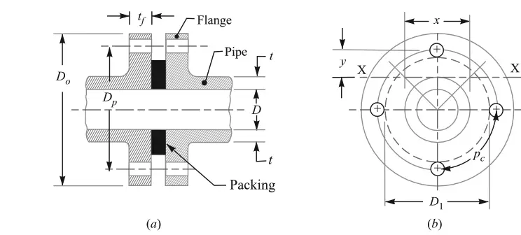
As we mentioned above the fluid pressure acts at the leaking point, which is the bolt holes. The circle touching these bolt holes is the effective diameter for the fluid pressure(p) to be concentrated. This circle is represented with the diameter D1 in the above diagram.
This diameter can be obtained (D1) by subtracting the bolt diameter(d1) from the pitch circle diameter(DP).
D1 =Dp–d1
∴ Let us calculate the Force trying to separate the two flanges apart,
F = (π/4) (D1)2 p
Let us assume the number of bolts as n and core diameter for the bolts as dc and the σt is the allowable stress for the material of the bolt.
∴ The resistive force to tear the bolts will be = (π/4) (dc)2 σt × n
from the above two equations, we can obtain the core diameter of the bolt(dc) and the number of bolts (n). Because of the symmetric section, the number of bolts should be even.
Circumferential Pitch of the bolt (pc)
The circumferential pitch of the bolts is given by (pc)= (π×Dp)/n
In order to make the circular flanged pipe joint leak-proof, we need to make the values of the circumferential pitch should be 20√d1 to 30√d1. (Where the d1 is bolt hole diameter on the flange).
A bolt hole of less than 16mm doesn’t need to make it leakproof.
Flange thickness (tf)
In order to determine the flange other parameters such as the thickness of the flange, we need to consider a segment of the flange as shown below figure.
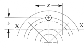
As shown above, it is assumed that each of the bolts supports one segment. The effect of joining these segments on the stresses induced is neglected.
From the above schematic diagram, the bending moment is taken about section X-X, which is tangential to the outside of the pipe.
Let the width of this segment is x and y is the distance of this section from the centre of the bolt as shown above diagram.
∴ The Bending moment on each bolt due to the force F
= F/n × y …….(a)
And let the σb is Bending or tensile stress for the flange material and Z is the Section modulus of the cross-section of the flange
then the resisting moment on the flange is = σb × Z ……..(b)
we can substitute the Z = (1/6) × x (tf)2
By equating these two equations (a), and (b), we can obtain the flange thickness tf.
This is how we can calculate the flange thickness. and following are the fixed dimensions as a rule of thumb for the flange design.
Nominal diameter of bolts, d = 0.75 t + 10 mm
Number of bolts, n = 0.0275 D + 1.6
Thickness of flange, tf = 1.5 t + 3 mm
Width of flange, B = 2.3 d
Outside diameter of flange (Do)=D+2t+2B
Pitch circle diameter of bolts (Dp)= D+2t+2d+12mm
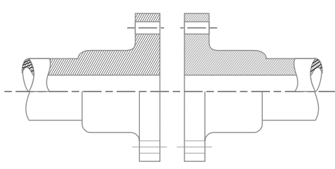
if the strength of the flange is not sufficient, then additional strength is provided by adding more thickness near the flange as shown in the below figure.
this additional thickness can be calculated from (t+tf)/2
In some other cases, the flange is supported by ribs to provide more strength to the flange as shown in the below figure.
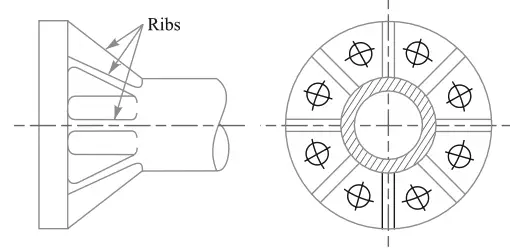
the ribs thickness can be calculated from (t+tf)/2.
Now let us solve a simple problem on the above topic.
Problem Statement: Calculate the dimensions for a circular flanged joint of cast iron pipe 250mm diameter to transport fluid with a pressure of 0.7 N/mm2.
Solution:
Give data is:
Pipe diameter D =250mm
Pipe inside pressure p = 0.7 N/mm2
Also, we know the cast iron tensile stress from the design handbook is σt = 14 N/mm2
We know the formula to calculate the pipe thickness based on the thin cylindrical formula from the previous article

The value of constant ‘C’, is given in the following table for the different metals such as cast iron, mild steel zinc, copper, and lead.
| Material | Cast iron | Mild steel | Zinc and Copper | Lead |
| Constant (C) in mm | 9 | 3 | 4 | 5 |
From this, we can calculate the thickness of the pipe
t = (0.7×250)/(2×14)+9 = 16mm.
With this thickness t of the pipe, we can calculate the fixed dimensions of the flange as we have mentioned in the formulas above.
Nominal diameter of bolts, d = 0.75 t + 10 = 0.75×16 + 10 = 22mm
Number of bolts, n = 0.0275 D + 1.6 = 0.0275 x 250 +1.6 = 8.475 let us say 10 number of bolts to be on safe side.
Thickness of flange, tf = 1.5 t + 3 = 1.5 x 16 + 3 = 27mm
Width of flange, B = 2.3 d = 2.3 x 22 = 50.6 = let us say 57mm to be on safe side.
Outside diameter of flange (Do)=D+2t+2B = 250+(2×16)+(2×57) = 386mm
Pitch circle diameter of bolts (Dp)= D+2t+2d+12mm = 250+(2×16)+(2×22)+12 = 338mm
Circumferential pitch of the bolts (pc)= (π×Dp)/n = (3.14×338)/10 = 106.2mm
In order to make the circular flanged pipe joint leak-proof, we need to make the values of the circumferential pitch should be 20√d1 to 30√d1.
Where the d1 is bolt hole diameter on the flange. Let us take the d1 = d+3 = 22+3 = 25mm
Therefore
20√d1 = 20√25 = 100mm
30√d1 = 30√25 = 150mm
From above we have the Circumferential pitch of the bolts (pc) = 106.2 which lies between 100mm and 150mm, therefore the above design is leakproof and satisfactory.
Conclusion
We have expressed how to design a circular flanged pipe joint with help of a sample problem. Below we have mentioned a much more complicated problem statement to solve yourself. Let us know the answers in the comment section for the below sample problem.
Problem statement: A flanged pipe with an internal diameter of 200 mm is subjected to a fluid pressure of 0.35 N/mm2. The flange is connected by means of eight M 16 bolts. The pitch circle diameter of the bolts is 290 mm. If the thickness of the flange is 20 mm, find the working stress in the flange.
Solve this, I will help you if you need me.

Dear Sir or Madam,
I wanted to cite this article in my bachelor’s thesis but the author is not shown. Would you mind providing me with the information?
With kind regards,
Leif Kaiser
It is already available in the author section at the bottom of the article.
The Auther Name is Mentioned below.
Sundar Dannana
Author at Extrudesign.com
Link: https://extrudesign.com/how-to-design-a-circular-flanged-pipe-joint/
Published date: September 21, 2021