Modelling, Assembling and drafting in Creo can be exciting and fun. Creating BOM with Repeat Region in Creo can be pretty frustrating sometimes as it should not be since Creo is one the best CAD software for engineers who work with large assemblies and their drawings and BOMs. Let us not too worry about this and solve this with ease.
For people new to Creo, PTC Creo is a family or suite of CAD software, that supports product design for discrete manufacturers and is developed by PTC.
Creating BOM with Repeat Regions
We are not covering creating a new drawing template and sheet sizes. we are directly getting into creating tables and BOM for the assembly. And also our parts must contain and be assigned all the system parameters for drawings.
We will make a table and fill in the repeat region parameters to instruct the system to “pull” data from the various parts of the assembly based on these system parameters. The system will automatically add a new row for each unique item in our bill of materials.
Example: If you have a plate and 4 identical bolts, that counts as 2 unique items.
What is Repeat Region?

We need to create our table such that it expands upward using a repeat region. These special parameters will only exist in the first row. The repeat region tells the system to automatically duplicate that same row over and over until all objects in our assembly have been added. Configuring a repeat region is a bit confusing the first time through.
Quick Tables for BOM with Repeat Region
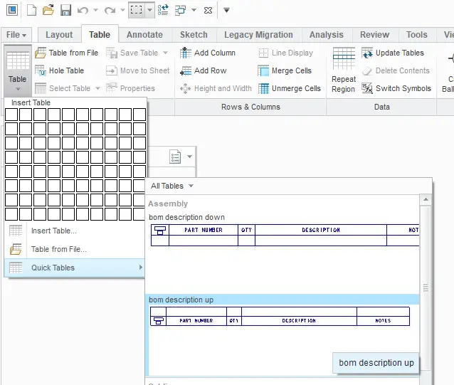
First, of all, we can actually choose from a pre-defined BOM and make modifications to suit our needs. These pre-defined BOMs already have repeat regions and most of the standard parameters defined.
- Access the Quick Table under the “Table” ribbon, and go to Quick tables. and insert any of the pre-defined table formats and place it on the drawing.
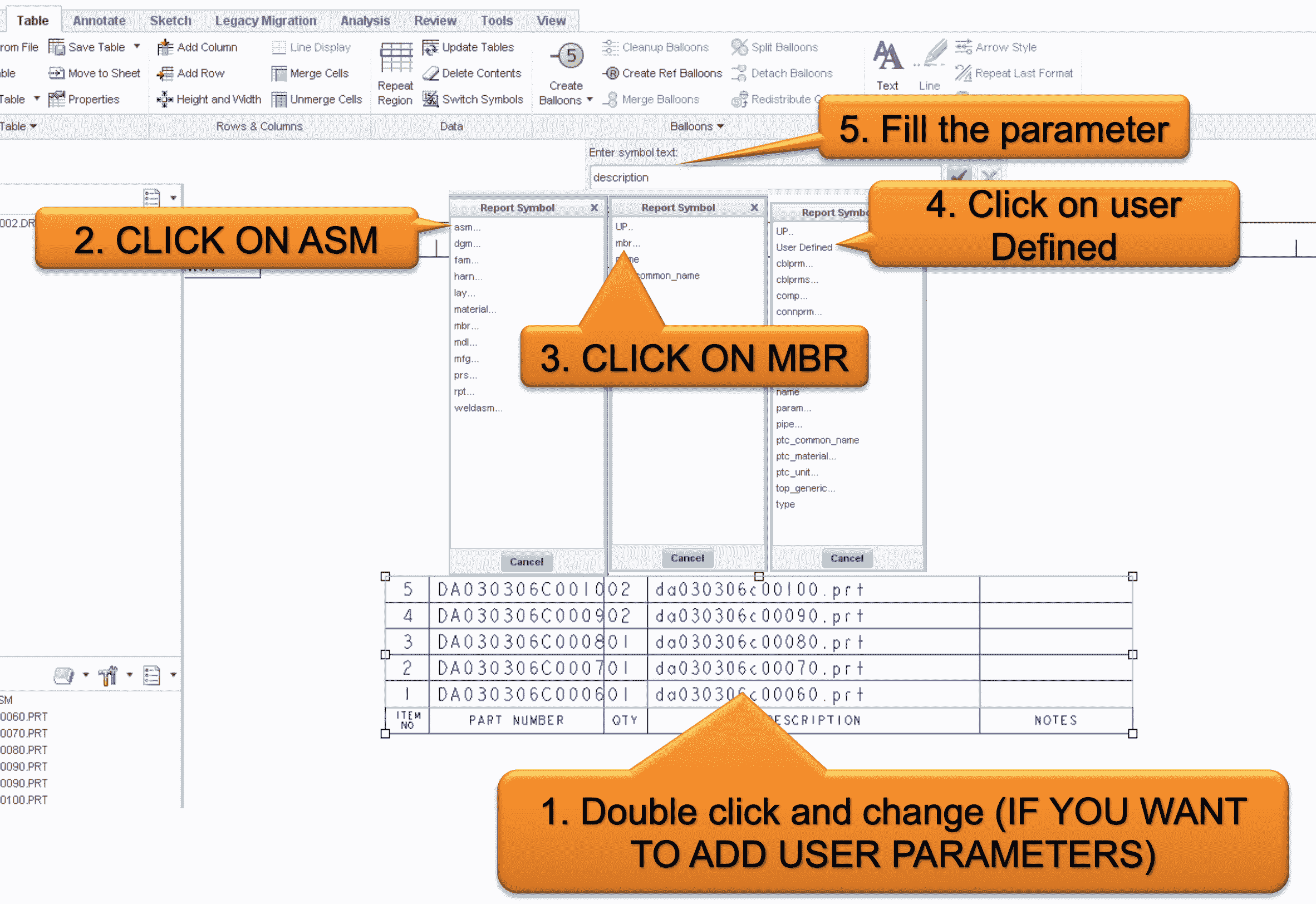
2. Editi the table attributes as follows.
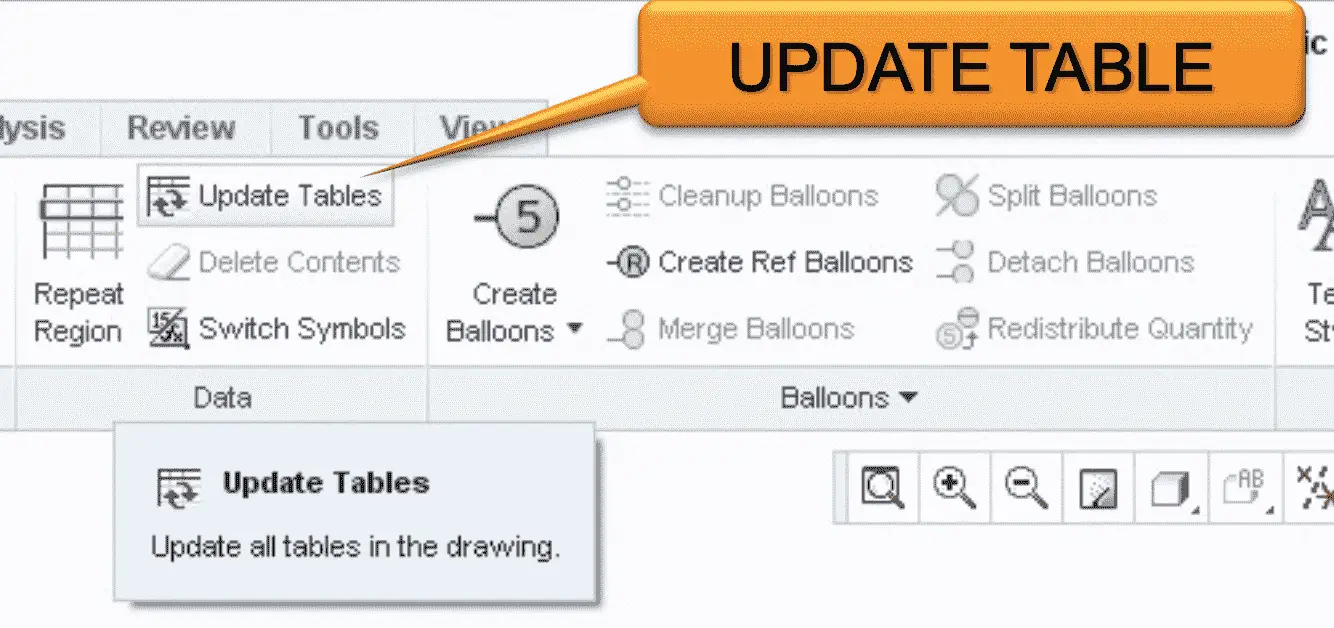
3. Update the tables
4. You can save this table format as .tbl file.
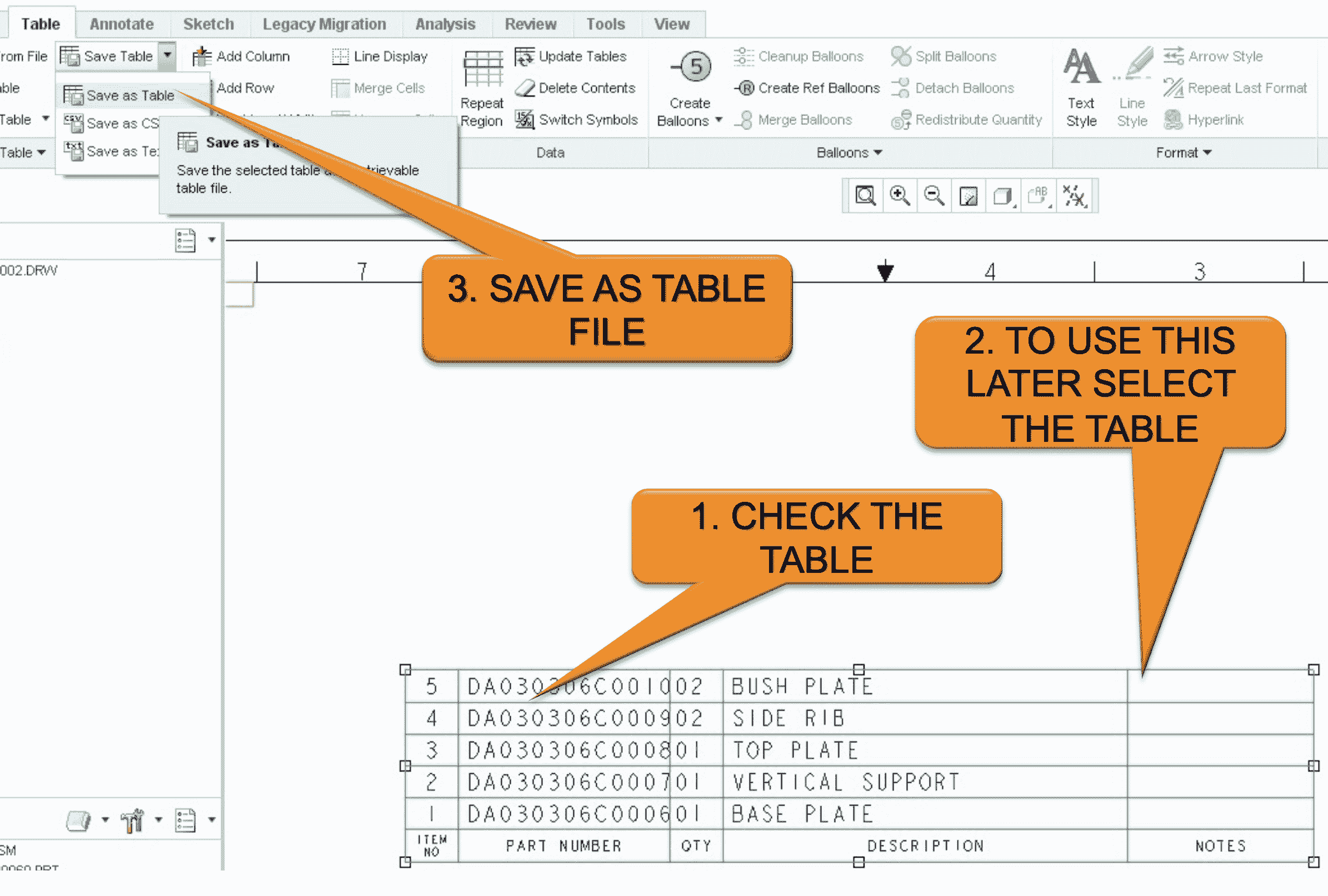
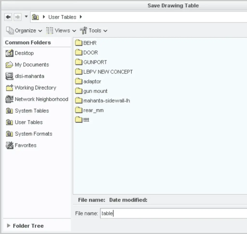
5. Importing this table again in the drawings.
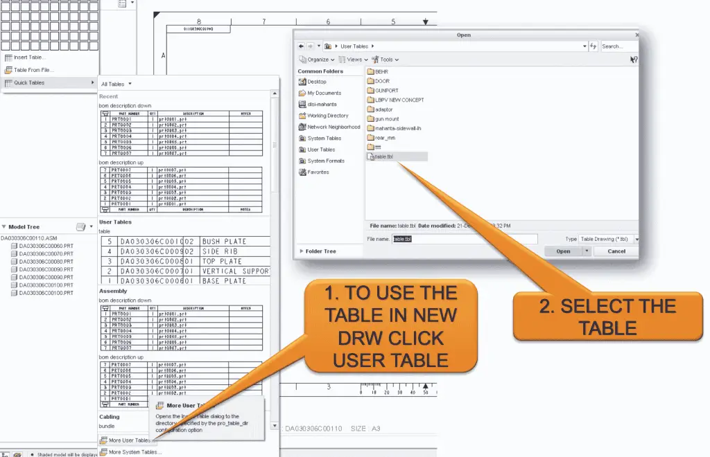
6. Position the table on the drawing.
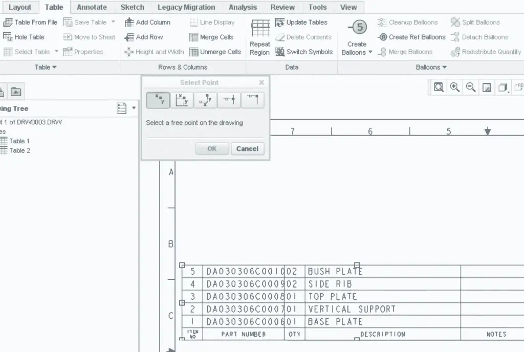
Advanced BOM with Repeat Regions
However, Quick tables really help to understand what’s happening in these tables rather than just copying them. Eventually, at some point, we need to get under the hood and really work within the BOM table from the scratch. Let’s do this.
- All BOMs need to have, at minimum, one column for the index. This will be our BOM item number (or find number as some call it). The parameter that drives this column is: &rpt.index
- Most BOMs also have a quantity column. The system will automatically add up identical items and place the total in this column. The parameter that drives this column is: &rpt.qty
- In our “start part” and “start assembly” we most probably defined some parameters of our own. Most commonly we create a parameter for “Description” and “Material”. We may also have ones for cage code, part number, vendor name, or some other data. We can extract any of these values using the following format: &asm.mbr.<Variable Name> For example, if we have defined a parameter called “test”, we would use &asm.mbr.test in our BOM table.
- Most companies list a part number for each item in the BOM. We can simply use the parameter: &asm.mbr.name to report the name of each part in the assembly. This will report the model name of each part in our assembly. Sometimes we don’t want the model name to appear in the “part number” column of our BOM. There are a couple of ways to override the standard model name in the BOM. This is a bit of a deeper topic. If you think we will need to override the model name often, mention it so we can discuss some options for building an automatic override option for us.
- There are other tricks we can use to extract material and mass properties data directly from the parts in our assembly. In fact, there’s a whole host of special pre-defined system parameters for each and every Creo part and assembly. If we need something other than the parameters presented here, just ask and I’ll be glad to discuss the other special parameters.
Once we’ve gotten the BOM to look exactly the way we want it, we will save the table for reuse later. We suggest you should put the saved table into your template or format files and they’ll automatically pop up whenever we started a new drawing. This is the way most engineers and drafters do it.
FLAT and RECURSIVE in Repeat Regions

The FLAT option in the Repeat Regions will list the sub-assembly names only (no parts inside these subassemblies). and the RECURSIVE option in the Repeat Regions will list all parts and the subassembly also.
If we need to remove the sub-assembly names and only want to include the parts only then we can apply filter &asm.mbr.type == PART on our repeat region.
Two Repeat Regions in one BOM
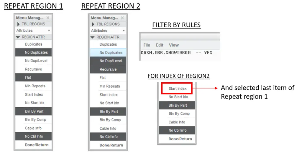
We can create two repeat regions for one single BOM to separate a particular type of component in the table as follows.
The example Assembly structure of the Main assy is as follows:
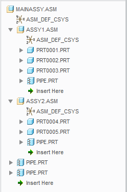
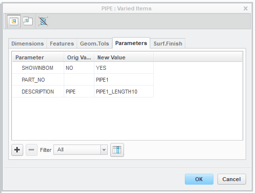
The Pipe.prt is modelled with flexibility and we need to introduce a parameter called “ShowinBom” and set it as a boolean value. I leave this parameter set to the default value “NO” and let us set this value to “Yes” only when it’s part of a sub-assy.
in the Drawing, now, we can use two repeat regions

Here you go the final result

This is how you can use Repeat Region to create BOM for your assemblies. Let us know what you think about this article in the comment section below.
Source: PTC community members Deepakjohsh, KshetrabasiMaha, BrianMartin.

Leave a Reply