In the previous article, we have discussed the classification of the Injection system. There we have listed the Fuel Injection system components. In this article, we are going to discuss
List of Main Components in Fuel Injection system
- Fuel tank
- Fuel Feed pump
- Injection pump
- Governors
- Fuel Injector
- Nozzle
Following is the schematic representation of a Fuel Injection System.
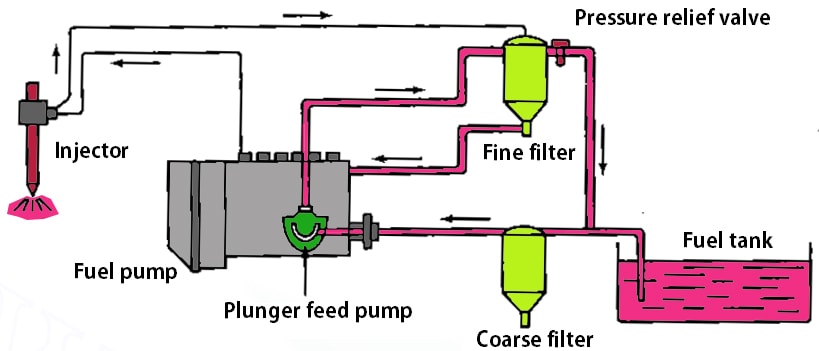
Fuel Tank
The Fuel tank is the fuel reservoir for the engine which holds the fuel and it will help to maintain the temperature of the fuel below the flash point. It also a corrosion-resistant and leakproof to pressures of at least 30 kPa. The fuel tank will be provided with a safety valve to relieve the excessive pressure. It will be able to dissipate the heat from the fuel coming from the engine.
Fuel Feed Pump
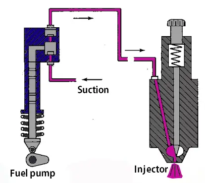
The Fuel feed pump
Injection Pump
The main function of the fuel Injection pump is to deliver the right amount of the fuel into the injector under high pressure. (usually, the range will be 120 to 200 bar) at the correct instance to the injector fitted in each cylinder head.
There are two different types of Injector pumps
- Jerk type pump
- Distributor type pump
1. Jerk type Pump
Following is a schematic representation of a Jerk type pump. It is a working example from Bosch fuel Injection pump.
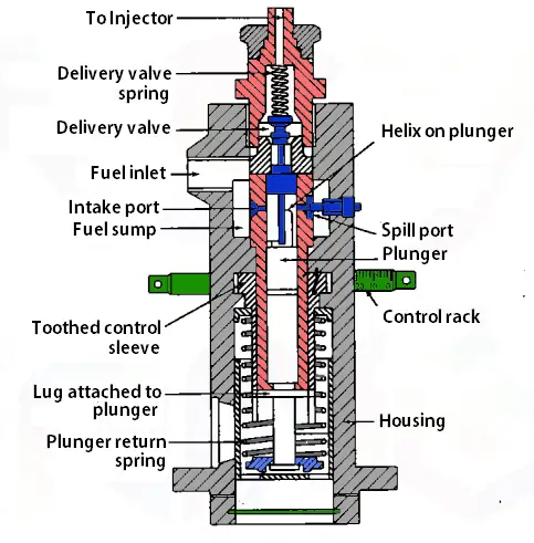
The above schematic representation is a single cylinder jerk type fuel injection system. In Jerk type pump there will be a reciprocating plunger operated by the camshaft.
2. Distributor Type Pump
Following is a schematic representation of a Distributor Type Pump.
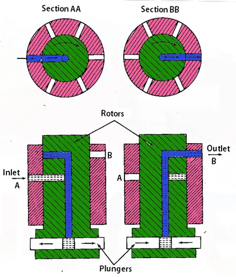
This pump has a single pumping element and the fuel will be distributed to each cylinder by means of the rotor. Inside the rotor, there is a long passage hole and also with two radial holes located at different holes. One hole is connected to the inlet and the second radial hole will be connected to the outlet as shown in the above schematic diagram.
Governors
In Compression-ignition Engines, the fuel delivered to the cylinders is independent of the injection pump characteristics and the air intake. The duty of the governor is to control the fuel quantity based on the load and limit the quantity of fuel when the engine running at very high speed with less load.
Governors are generally of two types
- Mechanical Governor
- Pneumatic governor
1. Mechanical Governor
The schematic representation of the mechanical Governor is shown below to illustrate the working principle.
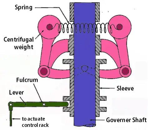
When the engine tends to run at high speed and crossing the speed limit, then the centrifugal weights fly apart and lifts the bell crank lever and moves the lever tip move downwards to actuate the control rack on the fuel injection pump and reduced the amount of fuel flow. This results in a reduction in the speed within the control limit. In the case of running at low speed, the lever tip moves upward direction and increases the fuel flow. This cycle will always happen back to back to keep the engine run smoothly.
2. Pneumatic governors
The schematic representation of the Pneumatic Governor is shown below to illustrate the working principle.
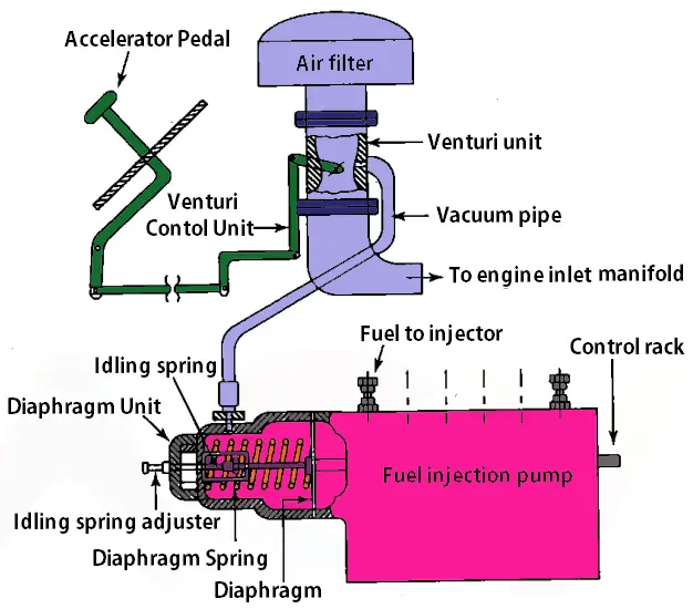
Pneumatic governor works with the working means as the fluid. There is a diaphragm actuated by means of vacuum. This vacuum will be controlled by the accelerator pedal. The diaphragm will be connected to the control rack on the fuel pump. The accelerator pedal movement determines the amount of the fuel goes into the cylinder.
Fuel Injector
The quick combustion will dependent on the well-designed fuel injector. A good fuel injector will atomize the fuel into fine droplets and increases the surface area of the droplets and helps for mixing of the subsequent combustion. The fuel injector is comprised of the following components.
- Needle valve
- Compression spring
- Nozzle
- Injector body
Following is a schematic cross-section representation of the fuel injector from BOSCH.
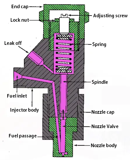
The fuel is supplied from the injection pump to the injector by means of a governor with sufficient force to lift the spring valve in the injector. The fuel will be sprayed as fine droplets into the cylinder.
Nozzle
The Nozzle is the part of the Injector through which the fuel is injected into the cylinder. Following is a schematic cross-section representation of the single hole Nozzle.
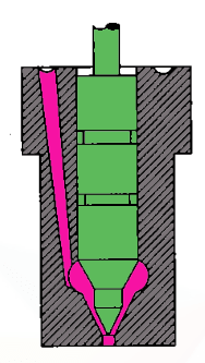
Any nozzle should fulfil a few requirements to be used in a CI engine. those are listed below
- Should be able to proper atomize the fuel. (Mixing of fuel with air in the combustion chamber)
- Fuel distribution in the cylinder against the cylinder pressure.
- Prevention of fuel from impinging directly on the walls of the combustion chamber or piston.
- Proper mixing of the fuel, even in the case of a non-turbulent type of combustion chamber.
These are the different types of components available in the injection system.
Conclusion
We have discussed the major components in the Fuel Injection system with a neat schematic representation with their working principles in this article. If you have any further thoughts on this topic, let us know in the comment section below.

i want to learn about injection tappet clearance
Thank you for the information on this page.
Welcome