Topic: What are the different Flatness testing methods for Surface Plates?
The surface plate is a massive solid structure, highly rigid in design which is having a true flatness of the surface.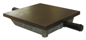
In metrology, the Surface plate is used as a measuring base or a datum surface for testing of flatness of surfaces. Surface plate forms the basis of the measurement. Surface plates are widely used in where the inspection is carried out.
So Surface plate will become a working standard. But how actually we can measure the flatness of the surface plate to ensure it can be used as a working standard.
What is actually Flatness means?
“Flatness is the minimum distance between the two planes that contain the surface”
Flatness testing is something similar to the straightness testing. There are various methods are available for flatness testing. We have listed them below.
Flatness testing Methods
- Using Two footed twisting Gauge/Three footed twisting Gauge
- Spirit Level Method
- Auto Collimator
- Beam Comparator
- Laser Beam
- Comparing with Liquid surface
- Interference Method
These are the available methods for flatness testing of the surface plates.
Note: Only two of the methods were discussed here(Comment below for the methods you want to know)
Comparing with Liquid surface
A surface of the liquid is used as the reference to measure the flatness of the surface plate. see the below apparatus.
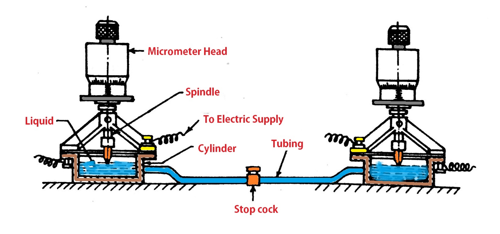
- There are two cylinders connected by a rubber tube at their bases. We can use mercury or a diluted soda solution as the liquid in the apparatus to take the liquid surface as the reference.
- There is micrometre head is fitted with a conical tip on their spindle on both of the cylinders. This tip will be going to have contact with the liquid surface in the cylinder by adjusting the spindle vertically with micrometre head.
- By this way, we can note down the micrometre readings on both cylinders by making contacting the liquid surface with a conical tip.
- Now move the second cylinder to another place on the surface plate.(While moving close the Stop cork to prevent the liquid flow between the two cylinders)
- Again adjust the micrometre heads to make the conical tips contact with the liquid surface.
- If there are any deviations in the surface plate there must be deviations in the micrometre readings too.
- By this way, we make one cylinder in the same position and moving the second cylinder to different positions on the surface plate to identify the deviations in the flatness.
- One quick caution is that the rubber tube should not contain any air bubbles.
- The electric supply is used to make sure the conical tip contacting the liquid surface or not.
Beam Comparator
Usually, Beam Comparator is used to determine the straightness of the surface.
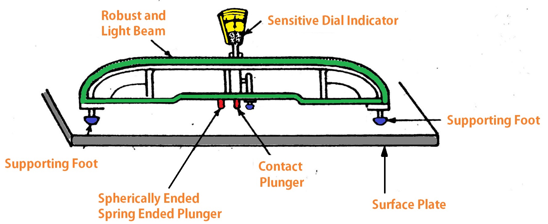
List of components in Beam comparator
- Light Beam
- Dial Indicator
- Plungers
- Supporting foots
Construction of Beam comparator
- A beam provided with three supported feet. One is fixed at the centre of the beam and the remaining two were fixed at both ends of the beam.
- The centre foot is fixed whereas the other two at the ends are relatively adjustable.
- A spherical plunger is also attached to at the middle (as shown in the above diagram) to prevent the beam from the overturn.
- A dial indicator is fixed on the beam with a plunger.
- all these feet and plungers must and should be lies within in a plane passing thru the endfeet.
Principle of Beam Comparator
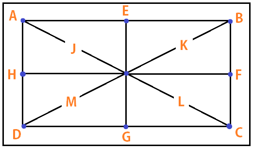
As you can see in the below picture the surface place spotted with some points(A, B, D, E, F, G, G, I, J, K, L, M). these places where we will put the feet and find out the straightness of the path AB, AC, AD…..
By comparing the straightness of each line joining the surface plate and with a known reference straight edge with the help of dial indicator.
In the same way, by displacing the middle feet over the surface plate on the generators(AB, AC, AD, HF)and take the observation in the dial indicator.
Here are their Generators representing on the surface plate.
AutoCollimator
AutoColimator is an Optical measuring Instrument used for straightness measurement ang angulr measurements aswell. This measuring device has high accuracy and sensitivity.
Following is the Schematic Diaram of the Auto Collimator apparatus.
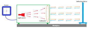
AutoCollimator consist of an collimator lens, light source and reflecting surface as shown in in the above schematic diagram.
Working Principle of AutoCollimator
As you can see the auto collimator consist of a light source and the collimator lense, which will produce the rays.
- The autocollimator and the reflecting mirror will be placed on the surface plate(Workpiece), which the flatness need to be tested.
- Now the reflecting surface need to be placed in the path of light rays along the length.
- The reading in the screen will show a dot.
- The dot represents that,is there any orientation in the reflecting mirror position or not. So that this orientation will be caused by the surface plate(Workpiece) flatness.

- So, the Dot showul be at the centre of X and Y axis, which means the surface is flat, check this for different positions on the surface plate(Workpiece).
- At the same time, you can use multiple mirrors on the surface plate to check the flatness as well.

This is how the Autocollimator works.
If you have any further dowubts on this topic, please let us know in the comments section below.
Tags: Metrology, flatness measurement, Testing Flatness of Surface Plates, Beam Comparator, Two-foot twist gauge, Comparing with Liquid surface, Mechanical Engineering Basics
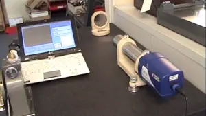
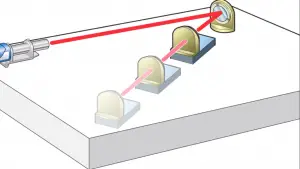

Flatness measurement by auto collimeter
Flatness measurement by auto collimeter
Hey, We have added , how to test the flatness of surface plate with Autocollimator as you asked. Thanks for your interest.
Hey, We have added, how to test the flatness of surface plate with Autocollimator as you asked. Thanks for your interest.
Please discuss about inferometer and its types…..
flatness measurement by spirit level
Spirit Level Method