A clutch is a machine member used to connect a driving shaft to a driven shaft so that the driven shaft may be started or stopped at will, without stopping the driving shaft. The use of a clutch is mostly found in automobiles. In the previous article, we have briefed about the different types of clutches. Let us see the Design of a Cone Clutch.

Clutch
A clutch is a machine member used to connect a driving shaft to a driven shaft so that the driven shaft may be started or stopped at will, without stopping the driving shaft. The use of a clutch is mostly found in automobiles. A little consideration will show that in order to change gears or to stop the vehicle, it is required that the driven shaft should stop, but the engine should continue to run. It is, therefore, necessary that the driven shaft should be disengaged from the driving shaft. The engagement and disengagement of the shafts is obtained by means of a clutch which is operated by a lever.
Friction Clutch
A Cone clutch is a type of friction clutch. A friction clutch has its principal application in the transmission of power of shafts and machines which must be started and stopped frequently. Its application is also found in cases in which power is to be delivered to machines partially or fully loaded. The force of friction is used to start the driven shaft from rest and gradually bring it up to the proper speed without excessive slipping of the friction surfaces. In automobiles, a friction clutch is used to connect the engine to the drive shaft.
In operating such a clutch, care should be taken so that the friction surfaces engage easily and gradually bring the driven shaft up to proper speed. The proper alignment of the bearing must be maintained and it should be located as close to the clutch as possible.
It may be noted that:
- The contact surfaces should develop a frictional force that may pick up and hold the load with reasonably low pressure between the contact surfaces.
- The heat of friction should be rapidly dissipated and the tendency to grab should be at a minimum.
- The surfaces should be backed by a material stiff enough to ensure a reasonably uniform distribution of pressure.
During the operation of a clutch, most of the work done against frictional forces opposing the motion is liberated as heat at the interface. It has been found that at the actual point of contact, a temperature as high as 1000°C is reached for a very short duration (i.e. for 0.0001 seconds). Due to this, the temperature of the contact surfaces will increase and may destroy the clutch.
Cone Clutch
A cone clutch, as shown in the following figure, was extensively used in automobiles, but nowadays it has been replaced completely by the disc clutch. It consists of one pair of friction surfaces only. In a cone clutch, the driver is keyed to the driving shaft by a sunk key and has an inside conical surface or face that exactly fits into the outside conical surface of the driven.
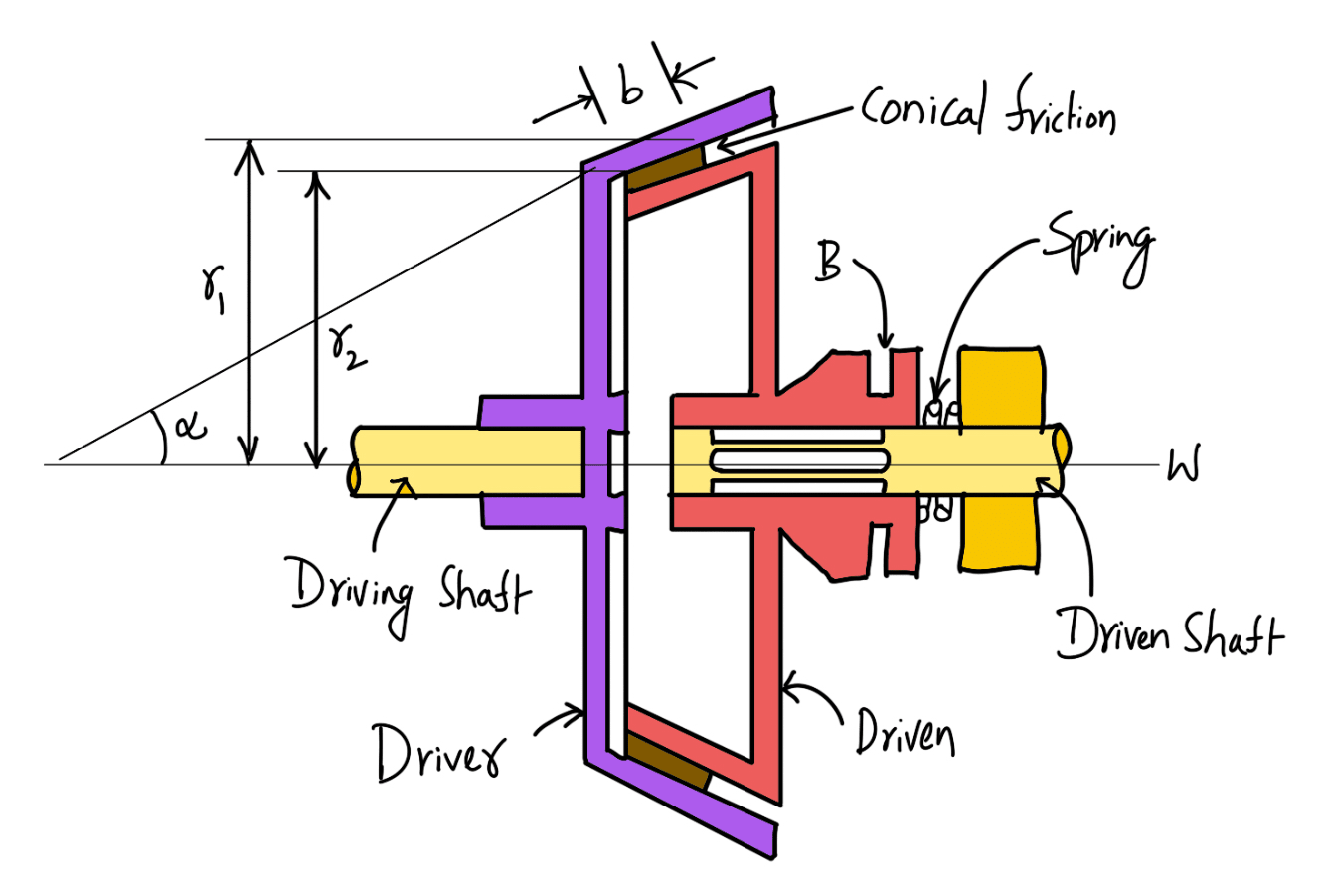
The driven member resting on the feather key in the driven shaft may be shifted along the shaft by a forked lever provided at B, in order to engage the clutch by bringing the two conical surfaces in contact. Due to the frictional resistance set up at this contact surface, the torque is transmitted from one shaft to another. In some cases, a spring is placed around the driven shaft in contact with the hub of the driven. This spring holds the clutch faces in contact and maintains the pressure between them, and the forked lever is used only for disengagement of the clutch.
The contact surfaces of the clutch may be metal-to-metal contact, but more often the driven member is lined with some material like wood, leather, cork asbestos, etc. The material of the clutch faces (i.e. contact surfaces) depends upon the allowable normal pressure and the coefficient of friction.
Design of a Cone Clutch
Consider a pair of friction surfaces of a cone clutch as shown in the following figure. A little consideration will show that the area of contact of a pair of friction surface is a frustrum of a cone.
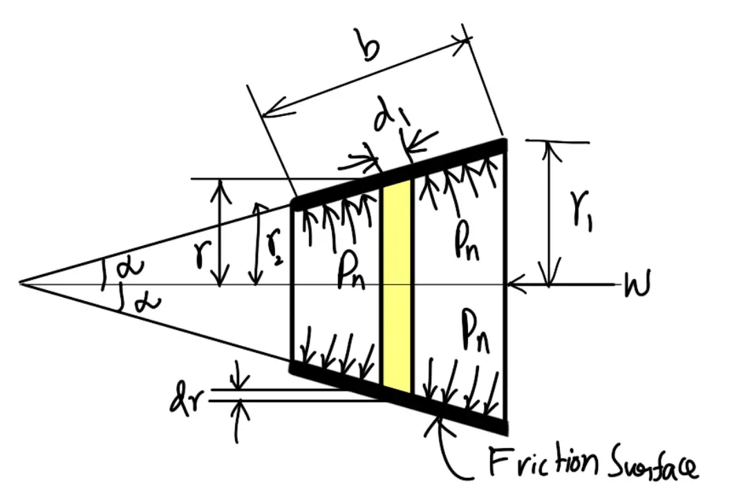
(Design of a Cone Clutch)
pn = Intensity of pressure with which the conical friction surfaces are held together (i.e. normal pressure between the contact surfaces)
r1 = Outer radius of friction surface,
r2 = Inner radius of friction surface,
R = Mean radius of friction surface = (r1 + r2)/2
α = Semi-angle of the cone (also called face angle of the cone) or angle of the friction surface with the axis of the clutch,
μ = Coefficient of friction between the contact surfaces, and
b = Width of the friction surfaces (also known as face width or cone face).
Consider a small ring of radius r and thickness dr as shown in the following figure. Let dl is the length of ring of the friction surface, such that,
dl = dr cosec α
Area of ring
= 2πr.dl = 2πr.dr cosecα
We shall now consider the following two cases:
- When there is a uniform pressure
- When there is a uniform wear
Considering uniform pressure
We know that the normal force acting on the ring,
δWn = Normal pressure × Area of ring
δWn = pn × 2π r.dr cosec α
and the axial force acting on the ring,
δW = Horizontal component of δWn (i.e. in the direction of W)
δW = δWn × sinα
δW = pn × 2πr.dr cosec α × sinα
δW = 2π × pn .r. dr
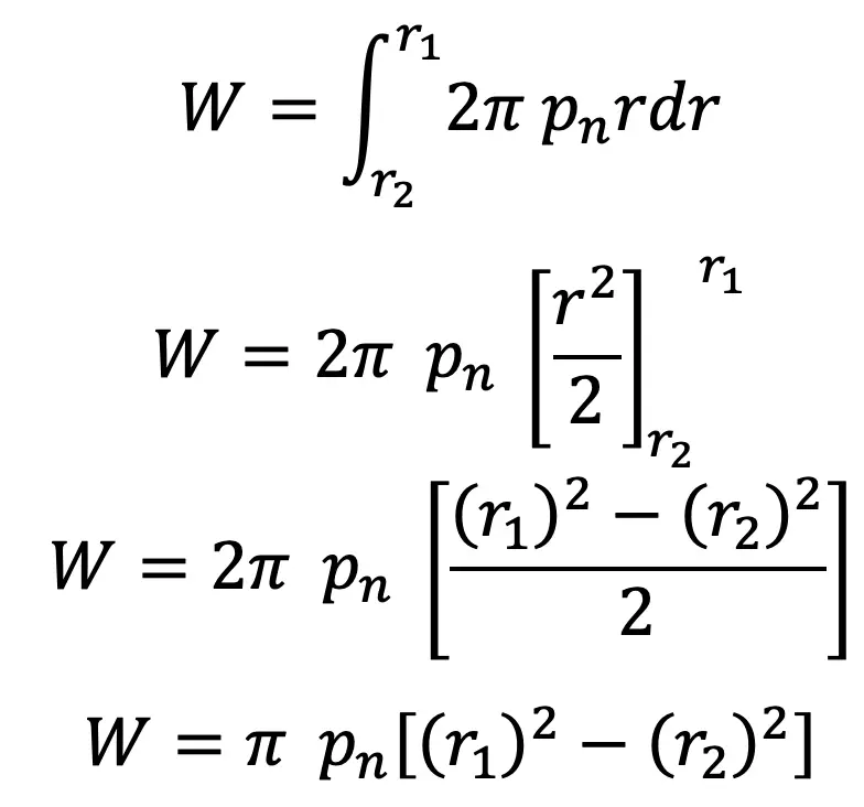
∴ Total axial load transmitted to the clutch or the axial spring force required,
and

…. equation (1)
We know that frictional force on the ring acting tangentially at radius r,
Fr = μ. δ Wn
Fr = μ. pn × 2π r. dr cosec α
∴ Frictional torque acting on the ring,
Tr = Fr × r
Tr = μ. pn × 2π r. dr cosec α × r
Tr = 2π μ.pn cosec α.r2 dr
Integrating this expression within the limits from r2 to r1 for the total frictional torque on the clutch.
∴ Total frictional torque,
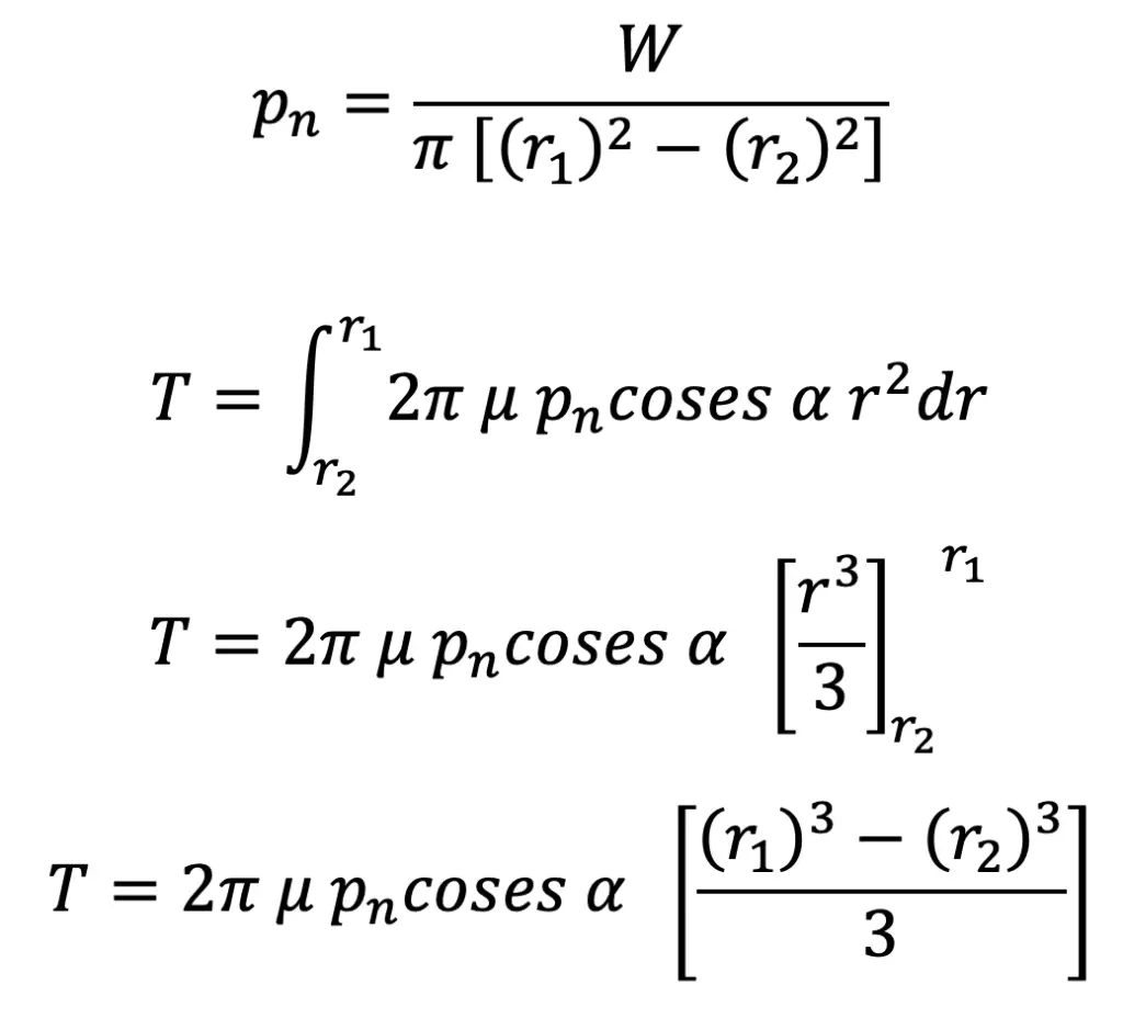
Substituting the value of pn from equation, we get

…. equation (2)
Considering Uniform Wear
In the above figure, let pr be the normal intensity of pressure at a distance r from the axis of the clutch.
We know that, in case of uniform wear, the intensity of pressure varies inversely with the distance.
pr.r = C (a constant)
pr =C / r
We know that the normal force acting on the ring,
δWn = Normal pressure × Area of ring
δWn = pr × 2πr.dr cosec α
and the axial force acting on the ring,
δW = δWn × sinα = pr × 2πr. dr cosec α × sin α
δW = 2π × pr.r dr
δW = 2π × (C÷r) × r.dr
δW = 2π C.dr
∴ Total axial load transmitted to the clutch,
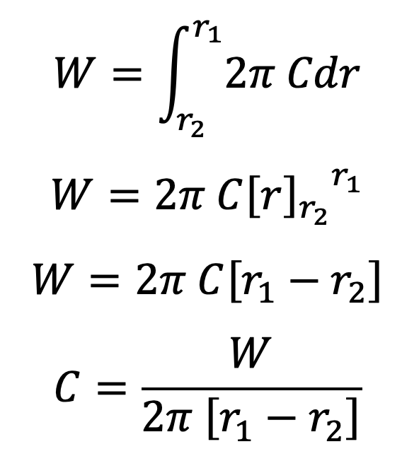
…. equation (3)
We know that frictional force on the ring acting tangentially at radius r,
Fr = μ . δWn
Fr = μ. pr × 2π r. dr cosec α
∴ Frictional torque acting on the ring,
Tr = Fr × r = μ.pr × 2π r.d r cosec α × r
Tr = μ × (C ÷ r) × 2πr . dr cosec α × r
Tr = 2 π μ . C cosec α × r dr
Integrating this expression within the limits from r2 to r1 for the total frictional torque on the clutch.
∴ Total frictional torque,
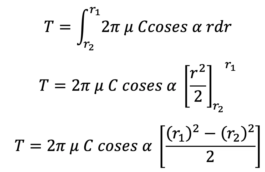
Substituting the value of C from above equation(3) , we have
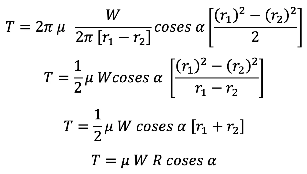
…. equation (4)
where
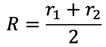
Since the normal force acting on the friction surface, Wn = W cosec α, therefore the equation may be written as
T = μ Wn R
The forces on a friction surface, for steady operation of the clutch and after the clutch is engaged, is shown in the following (a) and (b) respectively.
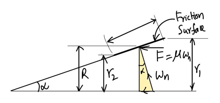
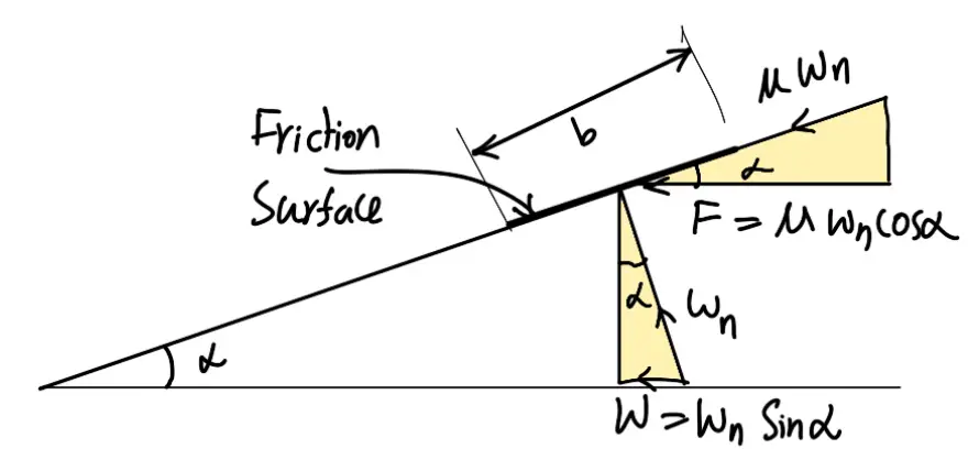
From the figure (a)
r1 – r2 = b sin α
R = (r1 + r2)/2
r1 + r2 = 2R
From equation (1), normal pressure acting on the friction surface,
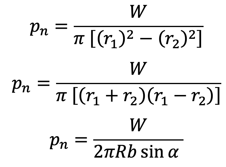
Or we can also write
W = pn × 2π R .b sinα
W = Wn sinα
where
Wn = Normal load acting on the friction surface = pn × 2πR . b
Now the equation (4) may be written as
T = μ (pn × 2π R b sinα) R cosecα
T = 2π μ . pn R2b
Important Points for Design of a Cone Clutch
The following points may be noted for the Design of a Cone Clutch:
- The above equations are valid for steady operation of the clutch and after the clutch is engaged.
- If the clutch is engaged when one member is stationary and the other rotating (i.e. during engagement of the clutch) as shown in the above figure (b), then the cone faces will tend to slide on each other due to the presence of relative motion. Thus an additional force (of magnitude μ.Wn cos α) acts on the clutch which resists the engagement, and the axial force required for engaging the clutch increases.
∴ Axial force required for engaging the clutch,
We = W + μ. Wn cosα
We = Wn . sinα + μ Wn cosα
We = Wn (sinα + μ cosα)
It has been found experimentally that the term (μ Wn. cos α) is only 25 percent effective.
We = Wn sinα + 0.25 μ Wn cosα
We = Wn(sinα + 0.25μ cosα)
- Under steady operation of the clutch, a decrease in the semi-cone angle (α) increases the torque produced by the clutch (T ) and reduces the axial force (W). During engaging period, the axial force required for engaging the clutch (We) increases under the influence of friction as the angle α decreases. The value of α can not be decreased much because smaller semi-cone angle (α) requires larger axial force for its disengagement.
If the clutch is to be designed for free disengagement, the value of tan α must be greater than μ. In case the value of tan α is less than μ, the clutch will not disengage itself and axial force required to disengage the clutch is given by
Wd = Wn (μ cosα – sinα)
This is all about Design of a Cone Clutch. Let us know what you think about this article in the comment section below.

Leave a Reply