A clutch is a machine member used to connect a driving shaft to a driven shaft so that the driven shaft may be started or stopped at will, without stopping the driving shaft. The use of a clutch is mostly found in automobiles. In the previous article, we have briefed about the different types of clutches. Let us see the Design of a Centrifugal Clutch.

Clutch
A clutch is a machine member used to connect a driving shaft to a driven shaft so that the driven shaft may be started or stopped at will, without stopping the driving shaft. The use of a clutch is mostly found in automobiles. A little consideration will show that in order to change gears or to stop the vehicle, it is required that the driven shaft should stop, but the engine should continue to run. It is, therefore, necessary that the driven shaft should be disengaged from the driving shaft. The engagement and disengagement of the shafts is obtained by means of a clutch which is operated by a lever.
Friction Clutch
A Centrifugal Clutch is a type of friction clutch. A friction clutch has its principal application in the transmission of power of shafts and machines which must be started and stopped frequently. Its application is also found in cases in which power is to be delivered to machines partially or fully loaded. The force of friction is used to start the driven shaft from rest and gradually bring it up to the proper speed without excessive slipping of the friction surfaces. In automobiles, a friction clutch is used to connect the engine to the drive shaft.
In operating such a clutch, care should be taken so that the friction surfaces engage easily and gradually bring the driven shaft up to proper speed. The proper alignment of the bearing must be maintained and it should be located as close to the clutch as possible.
It may be noted that:
- The contact surfaces should develop a frictional force that may pick up and hold the load with reasonably low pressure between the contact surfaces.
- The heat of friction should be rapidly dissipated and the tendency to grab should be at a minimum.
- The surfaces should be backed by a material stiff enough to ensure a reasonably uniform distribution of pressure.
During the operation of a clutch, most of the work done against frictional forces opposing the motion is liberated as heat at the interface. It has been found that at the actual point of contact, a temperature as high as 1000°C is reached for a very short duration (i.e. for 0.0001 seconds). Due to this, the temperature of the contact surfaces will increase and may destroy the clutch.
Centrifugal Clutch
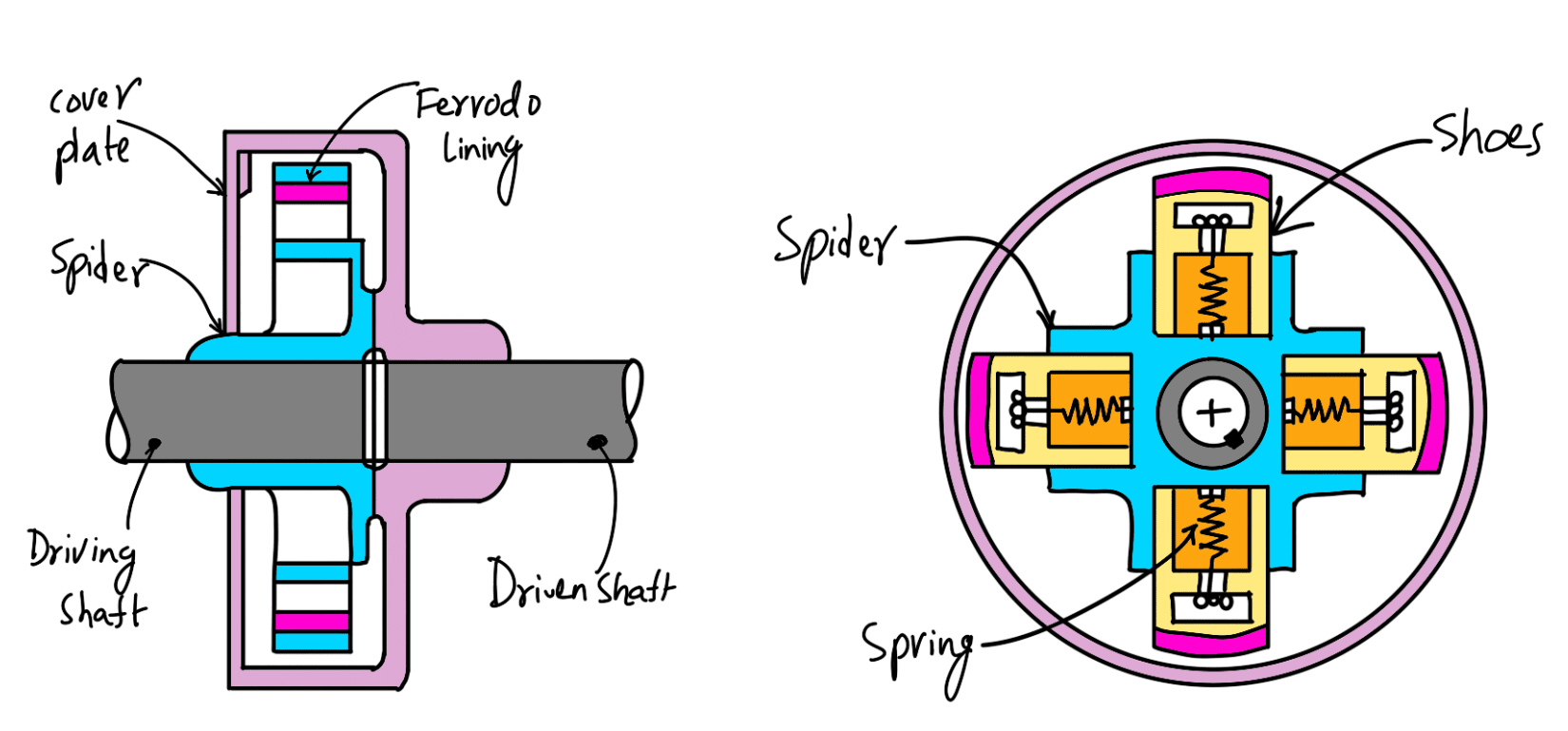
The centrifugal clutches are usually incorporated into the motor pulleys. It consists of a number of shoes on the inside of a rim of the pulley, as shown in the following figure. The outer surface of the shoes are covered with a friction material. These shoes, which can move radially in guides, are held against the boss (or spider) on the driving shaft by means of springs.

The springs exert a radially inward force which is assumed constant. The weight of the shoe, when revolving causes it to exert a radially outward force (i.e. centrifugal force). The magnitude of this centrifugal force depends upon the speed at which the shoe is revolving. A little consideration will show that when the centrifugal force is less than the spring force, the shoe remains in the same position as when the driving shaft is stationary, but when the centrifugal force is equal to the spring force, the shoe is just floating. When the centrifugal force exceeds the spring force, the shoe moves outward comes into contact with the driven member, and presses against it. The force with which the shoe presses against the driven member is the difference of the centrifugal force and the spring force. The increase in speed causes the shoe to press harder and enables more torque to be transmitted.
Design of a Centrifugal Clutch
In designing a centrifugal clutch, it is required to determine the weight of the shoe, size of the shoe and dimensions of the spring. The following procedure may be adopted for the design of a centrifugal clutch.
1. Mass of the shoes
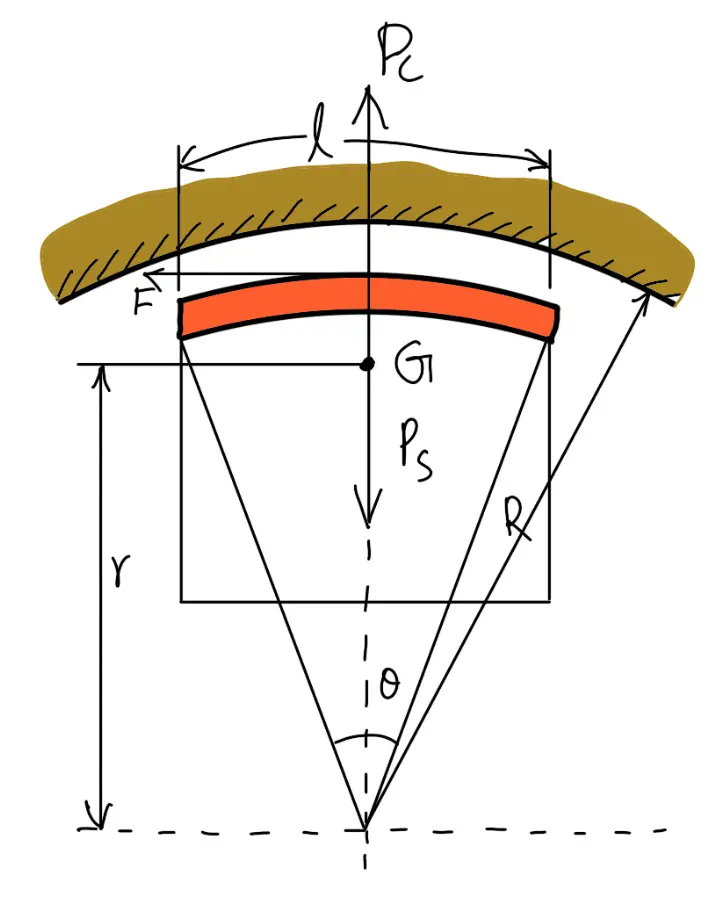
Consider one shoe of a centrifugal clutch as shown in the following figure.

(Design of a Centrifugal Clutch)
Let
m = Mass of each shoe,
n = Number of shoes,
r = Distance of centre of gravity of the shoe from the centre of the spider,
R = Inside radius of the pulley rim,
N = Running speed of the pulley in r.p.m.,
ω = Angular running speed of the pulley in rad / s = 2 π N / 60 rad/s,
ω1 = Angular speed at which the engagement begins to take place, and
μ = Coefficient of friction between the shoe and rim.
We know that the centrifugal force acting on each shoe at the running speed,
Pc = m. ω2.r
Since the speed at which the engagement begins to take place is generally taken as 3/4th of the running speed, therefore the inward force on each shoe exerted by the spring is given by
Ps = m. (ω1)2.r = m . (3ω/4)2.r = (9/16) m. ω2.r
∴ Net outward radial force (i.e. centrifugal force) with which the shoe presses against the rim at the running speed
= Pc – Ps = m. ω2.r – (9/16) m. ω2.r = (7/16) m. ω2.r
and the frictional force acting tangentially on each shoe,
F = μ (Pc – Ps)
∴ Frictional torque acting on each shoe
= F × R = μ (Pc – Ps)R
and total frictional torque transmitted,
T = μ (Pc – Ps) R × n = n . F . R
From this expression, the mass of the shoes (m) may be evaluated.
2. Size of the shoes
l = Contact length of the shoes
b = Width of the shoes,
R = Contact radius of the shoes. It is same as the inside radius of the rim of the pulley,
θ = Angle subtended by the shoes at the centre of the spider in radians
p = Intensity of pressure exerted on the shoe. In order to ensure reasonable life, it may be taken as 0.1 N/mm2.
We know that
θ = l/R
l = θ.R
l = (π/3) × R
∴ Area of contact of the shoe
= l × b
and the force with which the shoe presses against the rim
= A × p = l × b × p
Since the force with which the shoe presses against the rim at the running speed is (Pc – Ps), therefore
l × b × p = Pc – Ps
From this expression, the width of shoe (b) may be obtained.
3. Dimensions of the spring
We have discussed above that the load on the spring is given by
Ps = (9/16) m. ω2.r
The dimensions of the spring may be obtained as usual.
Example Problem on Design of a Centrifugal Clutch
Problem Statement: Design a Centrifugal Clutch to transmit 15 kW at 900 r.p.m. The shoes are four in number. The speed at which the engagement begins is 3/4th of the running speed. The inside radius of the pulley rim is 150 mm. The shoes are lined with Ferrodo for which the coefficient of friction may be taken as 0.25. Determine: 1. mass of the shoes, and 2. size of the shoes.
Answer:
Given data:
Power P = 15kW = 15 × 103 W
Speed N = 900 r.p.m.
number of shoes n = 4
Pulley rim Radius R = 150 mm = 0.15 m
Coefficient of friction μ = 0.25
1. Mass of the shoes
Let
m = Mass of the shoes.
We know that the angular running speed,

Since the speed at which the engagement begins is 3/4 th of the running speed, therefore angular speed at which engagement begins is
ω1 = 3ω/4 = (3 × 94.26)/4 = 70.7rad/s
Assuming that the centre of gravity of the shoe lies at a distance of 120 mm (30 mm less than R) from the centre of the spider, i.e.
r = 120mm =0.12m
We know that the centrifugal force acting on each shoe,
Pc = m. ω2.r = m × (94.26)2 × 0.12 = 1066 m N
and the inward force on each shoe exerted by the spring i.e. the centrifugal force at the engagement speed, ω1,
Ps = m. (ω1)2.r = m × (70.7)2 × 0.12 = 600 m N.
We know that the torque transmitted at the running speed,

We also know that the torque transmitted (T ),
T = μ (Pc – Ps) R × n
159 = 0.25(1066 m–600m) 0.15 × 4
159 = 70m
m = 2.27 kg
2. Size of the shoes
Let
l = Contact length of shoes in mm
b = Width of the shoes in mm
Assuming that the arc of contact of the shoes subtend an angle of θ = 60° or π / 3 radians, at the centre of the spider, therefore
l = (π/3) × R
l = (π/3) × 150
l = 157mm
Area of contact of the shoes
A = l.b = 157 × b mm2
Assuming that the intensity of pressure ( p) exerted on the shoes is 0.1 N/mm2, therefore force with which the shoe presses against the rim
= A.p = 157b × 0.1 = 15.7bN
We also know that the force with which the shoe presses against the rim
= Pc –Ps
= 1066m – 600m
= 466m
= 466 × 2.27
= 1058 N
From the above two equations, we find that
b = 1058 / 15.7 = 67.4mm
This is all about Design of a Centrifugal Clutch. Let us know what you think about this article in the comment section below.

Leave a Reply