A knuckle joint is a mechanical joint that helps to connect two rods that are under the action of tensile loads. In some cases, it is possible to join the rods with knuckle join if they are under compressive load with proper guided supports. In this article, we will discuss how to calculate the design parameters of the knuckle joint by considering the different modes of failure in this joint.
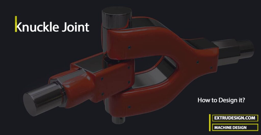
Knuckle Joint
A knuckle joint is a temporary fastening element since it can be readily disconnected for adjustments or repairs.
Some of the applications of Knuckle joint are
- Link of a cycle chain
- Tierod joint for roof truss
- Valve rod joint with eccentric rod
- Pump rod joint
- Tension link in bridge structure
- Lever and rod connections of various types
Construction of Knuckle Joint
The Knuckle Joint mainly contains 3 major parts, two rods, and a knuckle pin. The end of the first rod is made into an eye, and the end of the other rod is formed into a fork with an eye in each of the fork legs.
The knuckle pin passes through both the eye hole and the fork holes. This Knuckle pin will be secured by means of a collar and taper pin or split pin.
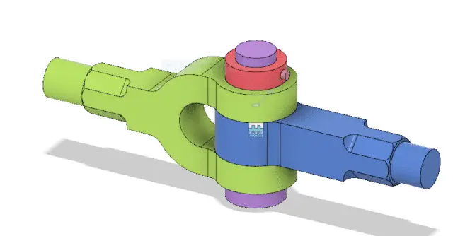
The knuckle pin may be prevented from rotating in the fork by means of a small stop, pin, peg, or snug.
In order to get a better quality joint, the sides of the fork and eye are machined, the hole is accurately drilled and the pin is turned. The material used for the joint may be steel or wrought iron.
Knuckle Joint Dimensions
The dimensions of various parts of the knuckle joint are fixed by empirical relations as given below. It may be assumed that all the parts should be made of the same material either mild steel or wrought iron.
Following is the schematic representation of the Knuckle Joint.
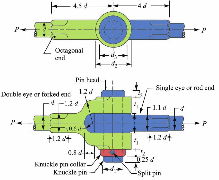
Let us assume
P = Tensile load acting on the rod,
d = Diameter of the rod,
d1 = Diameter of the pin,
d2 = Outer diameter of eye,
t = Thickness of single eye,
t1 = Thickness of fork
σt = Permissible Tensile stress of the joint material
τ = Permissible Tensile stress of the joint material
σc = Permissible crushing stress of the joint material
As we have take d is the diameter of the rod, then the diameter of the pin will be
d1 = d
The outer diameter of the eye,
d2 = 2 d
Diameter of knuckle pinhead and collar,
d3 = 1.5 d
The thickness of single eye or rod end (t) = 1.25 d
The thickness of fork (t1) = 0.75 d
The thickness of pinhead (t2) = 0.5 d
Other dimensions of the joint are shown in the above schematic representation of the knuckle Joint.
Methods of Failure in Knuckle Joint
In order to determine the strength of the joint for the various methods of failure, it is assumed that
- There is no stress concentration
- The load is uniformly distributed over each part of the joint.
Due to these assumptions, the strengths are approximate, however, they serve to indicate a well-proportioned joint.
Following are the various methods of failure of the joint
- Failure of the solid rod in tension
- Failure of the knuckle pin in shear
- Failure of the single eye or rod end in tension
- Failure of the single eye or rod end in shearing
- Failure of the single eye or rod end in crushing
- Failure of the forked end in tension
- Failure of the forked end in shear
- Failure of the forked end in crushing
Let us discuss these methods of failures in detail to determine and calculate the design parameters of the Knuckle Joint.
1. Failure of the solid rod under tension
By assuming the failure in the solid rod under tension we can determine the diameter of the rod.
We know that the cross-sectional Area resisting tearing inside the solid rod is given by
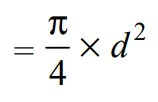
Since the rods are subjected to direct tensile load, the tearing strength of the rod will be the product of the induced tensile stress (σt) and the cross-sectional area that resist the tearing inside the rod.
We can write the relation as follows

Now in order to resist the load, we must Equate this tearing strength to load (P), We can write

From this relation, we can determine the diameter of the rod (d).
2. Failure of the knuckle pin in shear
Assuming the failure of the knuckle pin in shear will help us find out the diameter of the knuckle pin (d1).
Since the pin is in double shear, therefore a cross-sectional area of the pin under shearing will be

and the shear strength of the pin will be the product of the induced shear stress and the cross-sectional area of the pin under shearing. We can write this as follows.

Let us equate this to the load (P) acting on the rod, we have

From this relation, we can determine the diameter of the knuckle pin (d1).
Bending in Knuckle Pin
This assumes that there is no slack and clearance between the pin and the fork and hence there is no bending of the pin. But, in actual practice, the knuckle pin is loose in forks in order to permit angular movement of one with respect to the other.
Therefore the pin is subjected to bending in addition to shearing.
By making the diameter of the knuckle pin equal to the diameter of the rod (i.e., d1 = d), a margin of strength is provided to allow for the bending of the pin.
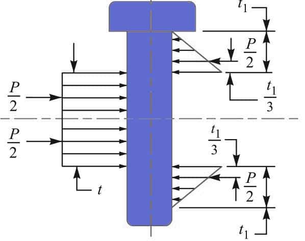
In this case, we need to consider the stress due to the bending of the pin. It is assumed that the load on the pin is uniformly distributed along the middle portion (i.e. the eye end) and varies uniformly over the forks as shown in the above figure.
Thus in the forks, a load P/2 acts through a distance of t 1 / 3 from the inner edge and the bending moment will be maximum at the center of the pin. The value of the maximum bending moment is given by
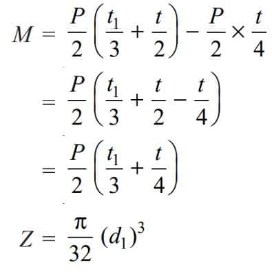
Where Z is the section modulus.
The Maximum bending (tensile) stress,
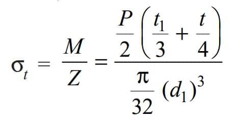
From this relation also, we can determine the value of d1.
3. Failure of the single eye or rod end in tension
The single eye or rod end may tear off due to the tensile load. We know that area resisting tearing
= (d2 – d1) t
The Tearing strength of a single eye or rod end
= (d2 – d1) t × σt
Equating this to the load (P) we have
P = (d2– d1) t × σt
From this equation, the induced tensile stress (σt ) for the single eye or rod end may be checked.
In case the induced tensile stress is more than the allowable working stress, then increase the outer diameter of the eye (d2).
4. Failure of the single eye or rod end in shearing
The single eye or rod end may fail in shearing due to tensile load. We know that area resisting shearing
= (d2 – d1) t
The Shearing strength of a single eye or rod end
= (d2 – d1) t × τ
Equating this to the load (P), we have
P = (d2 – d1) t × τ
From this equation, the induced shear stress (τ) for the single eye or rod end may be checked.
5. Failure of the single eye or rod end in crushing
The single eye or pin may fail in crushing due to the tensile load. We know that area resisting crushing
= d1 × t
The Crushing strength of a single eye or rod end
= d1 × t × σc
Equating this to the load (P), we have
P = d1 × t × σc
From this equation, the induced crushing stress (σc ) for the single eye or pin may be checked.
In case the induced crushing stress is more than the allowable working stress then increases the thickness of the single eye (t).
6. Failure of the forked end in tension
The forked end or double eye may fail in tension due to the tensile load. We know that area resisting tearing
= (d2 – d1) × 2 t1
The Tearing strength of the forked end
= (d2 – d1) × 2 t1 × σt
Equating this to the load (P), we have
P = (d2 – d1) × 2t1 × σt
From this equation, the induced tensile stress for the forked end may be checked
7. Failure of the forked end in shear
The forked end may fail in shearing due to the tensile load. We know that area resisting shearing
= (d2– d1) × 2t1
The Shearing strength of the forked end
= (d2 – d1) × 2t1 × τ
Equating this to the load (P), we have
P = (d2 – d1) × 2t1 × τ
From this equation, the induced shear stress for the forked end may be checked.
In case, the induced shear stress is more than the allowable working stress, the thickness of the fork (t1) is increased.
8. Failure of the forked end in crushing
The forked end or pin may fail in crushing due to the tensile load. We know that area resisting crushing
= d1 × 2 t1
The Crushing strength of the forked end
= d1× 2 t1 × σc
Equating this to the load (P), we have
P = d1× 2 t1 × σc
From this equation, the induced crushing stress for the forked end may be checked.
One important observation from the above failures of the joint, we see that the thickness of the fork (t1) should be equal to half the thickness of a single eye (t/2). But, in actual practice t1 > t/2 in order to prevent deflection or spreading of the forks which would introduce excessive bending of pin
Design Procedure of Knuckle Joint
The standard design parameters of the knuckle joint shown in the above image have been formulated after wide experience on a particular service.
These dimensions are of more practical value than the theoretical analysis. Thus, a designer should consider the empirical relations in designing a knuckle joint.
The following procedure should be adopted in order to design a knuckle joint.
- First of all, find the diameter of the rod by considering the failure of the rod in tension. We know that tensile load acting on the rod,

- After determining the diameter of the rod, the diameter of pin (d1) may be determined by considering the failure of the pin in shear. We know that load,

A little consideration will show that the value of d1 as obtained by the above relation is less than the specified value of the diameter of rod. So fix the diameter of the pin equal to the diameter of the rod.
- Other dimensions of the joint are fixed by empirical relations as discussed in above.
- The induced stresses are obtained by substituting the empirical dimensions in the relations as discussed in above. In case the induced stress is more than the allowable stress, then the corresponding dimension may be increased.
Let us solve a sample problem to design a Knuckle joint.
Example Problem Statement
Design a knuckle joint to transmit 150 kN. The design stresses may be taken as 75 MPa in tension, 60 MPa in shear, and 150 MPa in compression.
Answer:
Given data
Load (P) = 150kN = 150 × 103N
Permissible Tensile stress (σt) = 75 MPa = 75 N/mm2
Permissible Shear stress (τ) = 60 MPa = 60 N/mm2
Permissible Crushing stress (σc) = 150 MPa = 150 N/mm2
The joint is designed by considering the various methods of failure as discussed below :
1. Failure of the solid rod in tension
Let us say d = Diameter of the rod.
We know that the load transmitted (P),

150 × 103 = (π/4) × d2 × σt
150 × 103 = (π/4) × d2 × 75
150 × 103 = 59 d2
d2 = 150 × 103 / 59
d2 = 2540
d = 50.4
We got the diameter of the rod as 50.4. let us take this value as 52 to be on the safe side of the deisng.
Now the various dimensions are fixed as follows
Diameter of knuckle pin (d1) = d = 52 mm
Outer diameter of eye, d2 = 2 d = 2 × 52 = 104 mm
Diameter of knuckle pin head and collar d3 = 1.5 d = 1.5 × 52 = 78 mm
Thickness of single eye or rod end t = 1.25 d = 1.25 × 52 = 65 mm
Thickness of fork t1 = 0.75 d = 0.75 × 52 = 39 let us say 40 mm
Thickness of pin head t2 = 0.5 d = 0.5 × 52 = 26 mm
2. Failure of the knuckle pin in shear
Since the knuckle pin is in double shear, therefore load (P)

150 × 103 = (π/4) × (d1)2 × τ
150 × 103 = (π/4) × (52)2 × τ
150 × 103 = 4248 τ
τ = 150 × 103 / 4248
τ = 35.3 N/mm2 = 35.3 MPa
3. Failure of the single eye or rod end in tension
The single eye or rod end may fail in tension due to the load. We know that load (P),
P = (d2 – d1) t × σt
150 × 103 = (d2 – d1) t × σt
150 × 103 = (104 – 52) 65 × σt
150 × 103 = 3380 σt
σt = 150 × 103/3380
σt = 44.4 N/mm2 = 44.4 MPa
The induced tensile stress is 44.4 N/mm2 which is within the above specified permissible value, so the above-calculated dimensions are safe and good to go.
4. Failure of the single eye or rod end in shearing
The single eye or rod end may fail in shearing due to the load. We know that load (P),
P = (d2– d1) t × τ
150 × 103 = (d2– d1) t × τ
150 × 103 = (104 – 52) 65 × τ
150 × 103 = 3380 τ
τ = 150 × 103 / 3380
τ = 44.4 N/mm2 = 44.4 MPa
The induced shear stress is 44.4 N/mm2 which is within the above specified permissible value, so the above-calculated dimensions are safe and good to go.
5. Failure of the single eye or rod end in crushing
The single eye or rod end may fail in crushing due to the load. We know that load (P),
P = d1 × t × σc
150 × 103 = d1 × t × σc
150 × 103= 52 × 65 × σc
150 × 103= 3380 σc
σc = 150 × 103 / 3380
σc = 44.4 N/mm2 = 44.4 MPa
The induced crushing stress is 44.4 N/mm2 which is within the above specified permissible value, so the above-calculated dimensions are safe and good to go.
6. Failure of the forked end in tension
The forked end may fail in tension due to the load. We know that load (P),
P = (d2 – d1) 2 t1 × σt
150 × 103 = (d2 – d1) 2 t1 × σt
= (104 – 52) 2 × 40 × σt
= 4160 σt
∴ σt = 150 × 103 / 4160 = 36 N/mm2 = 36 MPa
The induced tensile stress is 36 N/mm2 which is within the above specified permissible value, so the above calculated dimensions are safe and good to go.
7. Failure of the forked end in shear
The forked end may fail in shearing due to the load. We know that load (P),
P = (d2 – d1) 2 t1 × τ
150 × 103 = (d2 – d1) 2 t1 × τ
150 × 103 = (104 – 52) 2 × 40 × τ
150 × 103 = 4160 τ
τ = 150 × 103 / 4160
τ = 36 N/mm2 = 36 MPa
The induced shear stress is 36 N/mm2 which is within the above specified permissible value, so the above-calculated dimensions are safe and good to go.
8. Failure of the forked end in crushing
The forked end may fail in crushing due to the load. We know that load (P),
P = d1 × 2 t1 × σc
150 × 103 = d1 × 2 t1 × σc
150 × 103 = 52 × 2 × 40 × σc
150 × 103 = 4160 σc
σc = 150 × 103 / 4180
σc = 36 N/mm2 = 36 MPa
The induced crushing stress is 36 N/mm2 which is within the above specified permissible value, so the above-calculated dimensions are safe and good to go.
Considering all the possible modes of failure in the knuckle joint, we have calculated the induced stress and seen that they are within the specified permissible stress values in the given problem statement.
Would you like to solve an example problem and design the knuckle joint?
Problem Statement: Design a knuckle joint for a tie rod of a circular section to sustain a maximum pull of 70 kN. The ultimate strength of the material of the rod against tearing is 420 MPa. The ultimate tensile and shearing strength of the pin material are 510 MPa and 396 MPa respectively. Determine the tie rod section and pin section. Take factor of safety = 6.
Solve this and let us know the answer in the comment section below. I will help you.

Leave a Reply