A final year project on “Corrosion Fatigue Analysis of Medium Carbon Steel C45″ to review whether the corrosive action affects the fatigue life of the material. This project paper is submitted by KESAVA SRIRAM to extrudesign.com.
ABSTRACT
- Corrosion fatigue testing was carried out on medium carbon steel C45.
- To review whether the corrosive action affects the fatigue life of the material.
- The analysis was carried out using corrosion fatigue testing machine of rotating bending beam type with the load applied at the mid-span of the specimen.
- Aqueous environmental conditions were synthetic seawater and 3% sodium chloride solution considering pH value as the major variable.
- The results showed that the fatigue life of the material was reduced more in synthetic seawater condition than in sodium chloride solution.
- SEM EDX analysis on the surface of the fractured specimen showed the deposition of chlorine which lead to crack nucleation and further quicker crack propagation.
Topic: Fatigue analysis, Corrosion in carbon steel C45, Corrosion fatigue analysis.
1. INTRODUCTION
- ASTM E742 ; Corrosion fatigue is defined as the “synergistic effect of fatigue and aggressive environment acting simultaneously, which leads to a degradation in fatigue behaviour”.
- Environmentally induced cracking
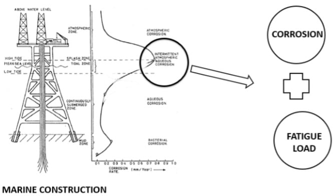
- Mechanical parts of nuclear power systems, steam and gas turbines, aircraft, marine structures, pipelines, and bridges, offshore drilling jigs, boilers, pressure vessels, are frequently subjected to cyclically varying loadsunder aggressive chemical environments.
- Failure happens at lower load levels due to the synergetic effect of both corrosion and cyclic loads.
- An initial damage (such as defect or void) present in a component experiences accelerated damage resulting in faster crack growth rate.
- Depends on how the corrosive environment is applied (spray or submerged).
2. Example for Corrosion Fatigue
3. Environmental Variables That Affects Corrosion Fatigue
4. Forms of Corrosion
5. Influence of Corrosion and Alternating Stress
6. Problem Identification
- It was observed that every material which was tested for the fatigue life in a corrosive environment was affected by the corrosivity of the aqueous environment.
- The corrosive action which has a significant effect on the failure must be considered in the material’s failure analysis.
- This analysis is also limited because of the unavailability of testing machines in local testing centers.
- Hence, it is necessary to find the corrosion fatigue life of the material before it is used in naval, marine and offshore constructions as well as in chemical industries.
7. Proposed System
- The material is tested using a rotating beam testing machine with a load applied at the mid-span.
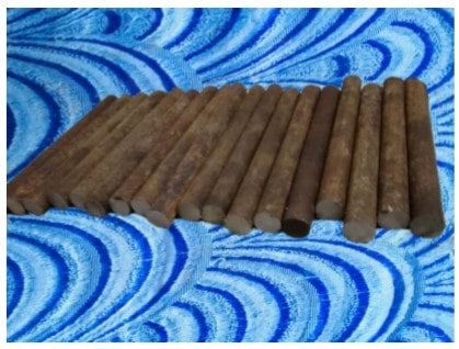
- In this project, common material which finds the application as shafts, spindles, studs and other automotive parts is selected for the analysis.
- When the materials under cyclic loading used in the aqueous condition, fatigue failure may be accelerated.
- This aqueous condition can be due to leakage from the pipes, chemicals overflow in industries also in offshore constructions such as platforms, drill rigs, etc., this condition is created by the oceanic seawater that splashes on the metals used for construction.
8. Testing Methodology
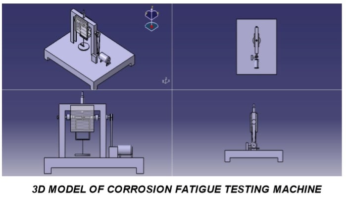
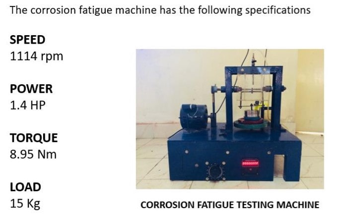
- The corrosion fatigue machine is of rotating-beam type in which the load is applied at the mid-span of the specimen using a hanger.
- It was designed based on RR Moore type fatigue testing machine and also considering the cost used to fabricate.
- The 3D model of the machine is shown in the below figure.
- ASTM PRO1960-60
9. Machine Specifications
10. Specimen Design
- The specimen is a design based on the specimen used for R R Moore rotating-beam type testing.
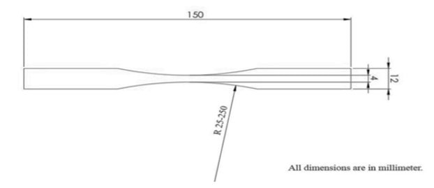
- The midsection of the specimen should be grooved with a radius of curvature ranging from 25- 250 mm. The midsection of the specimen is 4mm and the outer diameter of the specimen to be held by the chuck is 12mm.
11. Material Selection
Medium Carbon Steel C45
- High tensile properties and hardness
- Application – gears, shafts, axles, studs, etc,
- Corrosive Environment
- In offshore applications, corrosive actions due to splash of oceanic water on it.
- The continuous flow of any fluid (such as chemicals, oil, greases, etc.,)
12. Chemical Composition
13. Mechanical Properties
14. Load Calculations
The load calculations include the amount of stress that should be applied on the specimen for testing. In this setup, bending stress is acting on the specimen at the mid-section must be calculated for maximum deflection.
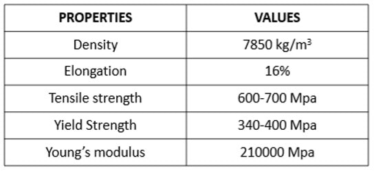
From the design data book, we know that σb = 0.6 σu ≤ σy
Where,
σb – Bending stress (MPa)
σu – Ultimate tensile strength (MPa)
σy – Yield strength (MPa)
therefore,
σb= 0.6 × 700 = 420 MPa (for maximum deflection)
Deflection, Y = PL3 / 48 EI
Moment of inertia, I= π ×d4/ 64 = π ×44/ 64 = 12.56 mm4
Therefore,
Y = PL3 /48 EI = P × 1204 / (48 × 210000 × 12.56) = 0.0136P
We know, Maximum bending moment,
Mb = PL / 4
=P×120/4=30P
Also, maximum bending stress,
σb = (Mb × Y)/ I
420 = (30P × 0.0136P) / 12.56
420 = 0.0324P2
P2 = 12962.96 Hence, P = 113.85 N = 11.6 Kg
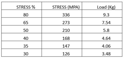
Load to be applied for different stress levels are listed below
15. Load Distribution Data
16. Corrosion Fatigue Analysis Experimental Procedure
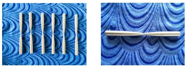
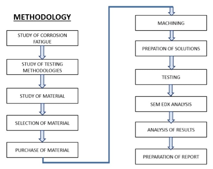
- The selected material is first to cut into the required length for the machining process. The raw material cut into pieces.
- The raw materials are machined as per the dimension’s specimen specified above. Also rubbed with an emery sheet to produce a smooth surface.
- Totally 12 specimens are machined in order to test the specimens in different aqueous conditions. Six specimens for testing in artificial seawater and the next six specimens for testing in 3% sodium chloride solution are machined.
- The additives such as synthetic seawater and 3% sodium chloride solution required for the testing is prepared with the specified composition.
- To start the experimental work, the storage tank is filled up with synthetic seawater.
- Now the workpiece (specimen), which is machined based on the standard dimension is fixed between the chucks along with the ring used for loading.
- Then, the corrosion chamber is fixed to the machine set up around the specimen.
- The load is applied at the centre of the specimen through the weight hanger on the basis of the load calculation as well as the valve is opened for the flow of fluid.
- Once the specimen is fixed, the machine and the pump is switched on. Hence, the motor starts to rotate as well as the corrosive liquid is splashed on the specimen.
- At a certain number of cycles, the specimen gets fractured and the loaded weight on the specimen falls on the limit switch which is fitted at the base. Thus, the motor gets turned off.
- After the fracture, a number of cycles is noted down from the digital counter.
- This procedure is followed for the first six specimens in aqueous environmental condition with artificial seawater and the next set of specimens in 3% sodium chloride solution.
17. Corrosion Fatigue Analysis Result
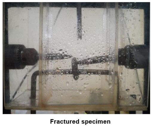
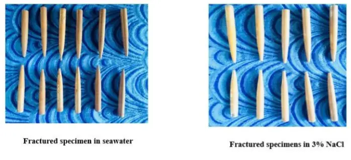
The material tested in the machine fractured at the grooved position where the load is applied as well as at the liquid air interface.
18. S-N Curve

Endurance limit: 30% of bending Stress –Synthetic seawater
35% of bending stress – 3% NaCl
Specimen tested in synthetic seawater corroded more than in 3%NaCl solution
19. SEM EDX Analysis
- To understand the crack structure and to observe the presence of external substances on the fractured surface SEM EDX analysis must be carried out on the specimen used for testing.
- The tested specimen is cut to 1cm from the fractured surface as shown in the below figure.
- Specimens fractured when 80% of the bending stress was applied and also fractured at the endurance limit in both the aqueous environment is used for this analysis.

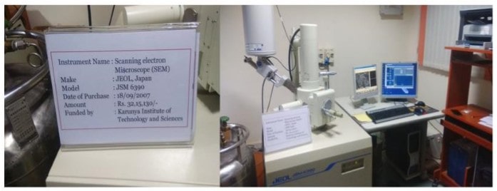
20. Scanning Electron Microscope
(Acknowledged by Karunya Institute of Technology and Science)
21. EDAX Results
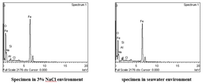
- The SEM EDX analysis was carried out on the fractured specimen to investigate the influence of corrosive fluid. The results are plotted in a graph as shown in the below figure.
- The Energy Dispersive X-ray Analyzer (EDAX) result of the tested specimen confirms the presence of chlorine element on the fractured surface in both the conditions which lead to quicker crack initiation and propagation.
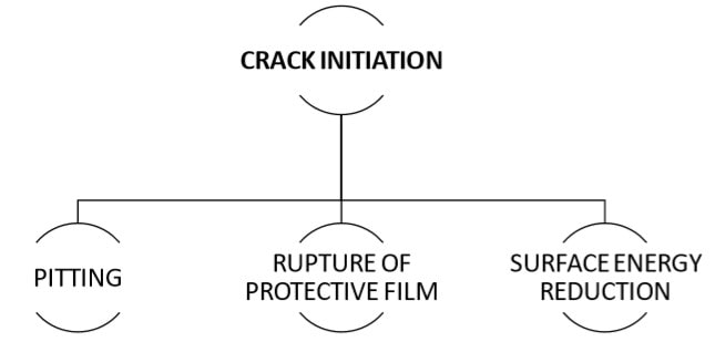
- Hence, it is clear that the crack is initiated due to nucleation of this chlorine on the pits and ruptures the film of the surface which helps for corrosion to occur.
- Also, the crack propagation will be quicker due to deposition of chlorine elements between the cracks.
- Studies show that the corrosion rate of Carbon steels and cast-iron increases significantly with as little as 0.5 mg/L chlorine and continues to increase as the residual increases.
22. SEM Results
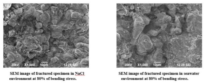
- The SEM images of the specimen which fractured at 80% of the bending stress in both the aqueous environment are shown in the below figure.
- Cracks and pits are more in number
- White spots – oxidation
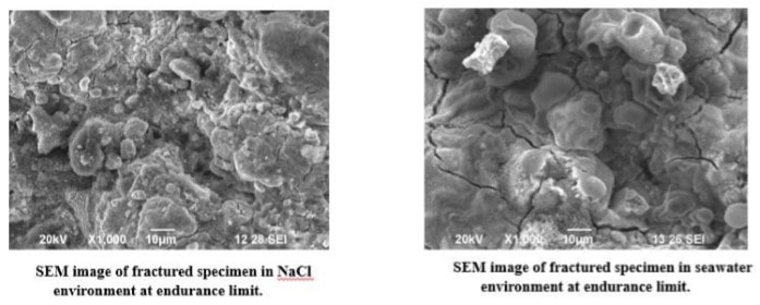
- The SEM images of the specimen which fractured at endurance limit in both the aqueous environment are shown in the below figure.
- Cracks are less in number
Conclusion
- It is observed that the material’s fatigue life is affected in the synthetic seawater condition more than the sodium chloride solution.
- SEM EDX analysis shows the presence of chlorine on the surface of the specimen which leads to nucleation of corrosion pits while testing.
- This nucleation of corrosion pits leads to crack initiation and also quicker crack propagation.
- It is also observed that a corrosive layer is formed on the surface of the specimen soon after testing.
- The endurance limit of the material is obtained at 147MPa bending stress in 3% NaCl solution environment than in synthetic seawater condition (126MPa bending stress).
- The SEM images of the specimen tested showed that the material had undergone oxidation and more number of pits was formed on the surface which leads to crack initiation.
- This material can be used in the naval and marine applications where the pH value of the ocean ranges from 7.4 – 8.2.
- The allowable bending stress for the material in these regions was 30% – 35% of the bending stress to have more fatigue life considering the corrosive environment.
Future Scope
- The same material can be tested in an acidic aqueous environment for corrosion fatigue life to find the application of the material in chemical industries.
- In chemical industries, the material may undergo a chemical reaction which may tend to create some forms of corrosion.
References
- Ragab , H.Alawi and K.Sorein, “ Corrosion fatigue of steel in various aqueous environments”, 17 February 1989.
- Dr. Abbas M.R. Al-Marafie, “Corrosion fatigue of some carbon steels in main aqueous environments in Kuwait”, 1986.
- H.H. Lee and H.H. Uhlig, “Corrosion fatigue of type 4140 High Strength Steel”, Metallurgical Transactions -2950, Volume 3, November 1972.
- C.E. Jaske, J.H. Payer and V.S. Balint, “Corrosion fatigue of metals in marine environments”, July 1981.
- Sree Phani Chandar Reddy, “Modeling of environmentally assisted fatigue crack growth behavior”, May 2015.
- Chinnaiah Madduri and Raghu V. Prakash, “Corrosion fatigue crack growth studies in Ni-Cr-mn steel”, International Journal of Mechanical and MechatronicsEngineering, Volume 4, Number 12, 2010.
- U R. Evans and M. Tchorabdji , “The mechanism of corrosion fatigue of mild steel”, 23 February, 1946.
- Zahida Begum , A. Poonguzhali , Ranita Basu , C. Sudha , H. Shaikh, R.V. Subba Rao , Awanikumar Patil , R.K. Dayal, “Studies of the tensile and corrosion fatigue behaviour of austenitic stainless steels”, Corrosion Science 53 (2011) 1424–1432,January 2011.
- O. K. Chopra, W. J. Shack, “Environmental effects on fatigue crack initiation in piping and pressure vessel steels”, May 2001.
- A. Castagna and N. S. Stoloff, “The influence of environment on fatigue crack growth of an Fe3Al, Cr alloy”, Materials & Design, Volume 14, Number 1, 1993.
- C. Mabru, D. Bertheau, S. Pautrot, J. Petit, G. Henaff, “Influence of temperature and environment on fatigue crack propagation in a TiAl-based alloy”, EngineeringFracture Mechanics 64, pg. 23-47, 1999.
- S. suresh, G. F. Zamiski, and R. O. Ritchie, “Oxide-Induced crack closure: an explanation for near-threshold corrosion fatigue crack growth behavior”,Metallurgical Transactions A, Volume 12A, 1981.
- S. Suresh G. Palmer and R. E. Lewis, “The effect of environment on fatigue crack growth behavior of 2021 aluminum alloy”, Fatigue of Engineering metals andstructures, Vol. 5. No. 2, pg. 133-1 50, 1982.

Leave a Reply