In metal works, Wire drawing and tube drawing is a stretching of a metal or plastic or even glass material to the desired shape in continuous products such as wires and tubes. Let us discuss more details about this metalworking process in detail.

Wire Drawing Process
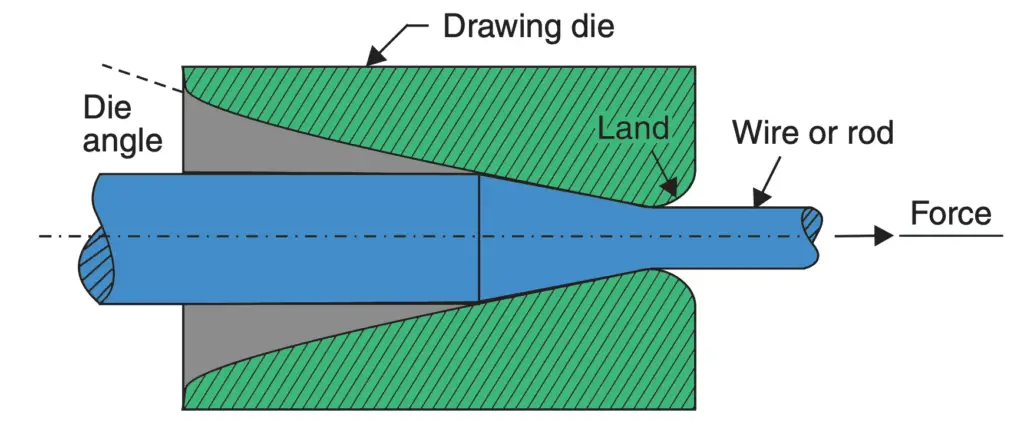
Wire drawing is a simple process. In this process, rods made of steel or non-ferrous metals and alloys are pulled through conical dies having a hole in the centre. The included angle of the cone is kept between 8 to 24°. As the material is pulled through the cone, it undergoes plastic deformation and gradually undergoes a reduction in its diameter. At the same time, the length is increased proportionately. The process is illustrated in the following figure.

- The dies tend to wear out fast due to the continuous rubbing of metal being pulled through it.
- Hence they are made of very hard materials like alloy steel, tungsten carbide or even diamond.
- In one pass, the reduction in the cross-sectional area achieved is about 25–30%.
- Hence in a wire drawing plant, the wire has to pass through several dies of progressively reducing diameter to achieve the required reduction in diameter.
- However as the wire passes through dies and undergoes plastic deformation, it gets strained hardened.
- Its strength increases and its capacity to further undergo plastic deformation decreases.
- Therefore during the entire run of the wire, from time to time, it has to be heated (and cooled) to remove the effect of work-hardening.
- This process is called “in-process annealing”.
- The aim is to make the material soft and ductile again so that the process of drawing may be smoothly carried out.
- The metal rods to be drawn into wires must be clean.
- If necessary, they are pickled in an acid bath to dissolve the oxide layer present on the surface.
- Its front end is then tapered down so that it may pass through the hole in the die which is firmly held in the wire drawing machine.
- The wire is drawn using several power-driven spools or rotating drums.
- During wire drawing, a great deal of heat is generated due to friction between the wire rod and the die.
- To reduce friction, dry soap or a synthetic lubricant is used.
- But despite reducing friction, the dies and drums may have to be water-cooled.
- The preferred material for dies is tungsten carbide but for drawing fine wire, the use of ruby or diamond dies is preferred.
- The drawing machines can be arranged in tandem so that the wire drawn by the previous die may be collected (in coil form) in sufficient quantity before being fed into the next die for further reduction in diameter.
- As the diameter becomes smaller, the linear speed of wire drawing is increased.
The major variable in the wire drawing process is
- Reduction ratio
- Die angle
- Friction
Improper control of these parameters will cause defects in the drawn material. Defects include centre cracking (as in extrusion and for the same reasons) and the formation of longitudinal scratches or folds in the material.
Tube Drawing Process
The above discussed ‘drawing’ process can also be used for tube drawing. Tube drawing does not mean manufacturing a tube from solid raw material. It means lengthening a tube by reducing its diameter. Various arrangements used for tube drawing are shown in the following figure.

(b) uses a floating mandrel that adjusts itself to the correct position because of its stepped contour.
- The method shown in the above figure (a) is the most common method used for tube drawing. A conventional tube drawing bench is used.
- The method shown in the above figure (b) employs a floating mandrel.
- The method shown in the above figure (c) uses a long circular rod to control the size of the tube bore.
- The method shown in the above figure (d) uses neither a mandrel nor a bar and controlling the size of the bore is difficult.
Tube Making Process
Tubes and pipes are required in large quantities by industries all over the world. Tubes are basically of
two types.
- Seamless Tubes (without any joint)
- Tubes with joints all along the length
Seamless tubes are made by processes such as casting, extrusion or rolling.
Tubes with joints are made by welding. Usually, the weld joint is made by an electric resistance welding process. such tubes are referred to as ERW tubes.
- The size of a tube or pipe is indicated by the size of its bore in mm.
- Since the requirement of tubes is so large, a special rolling process called Mannesmann rotary piercing process has been developed.
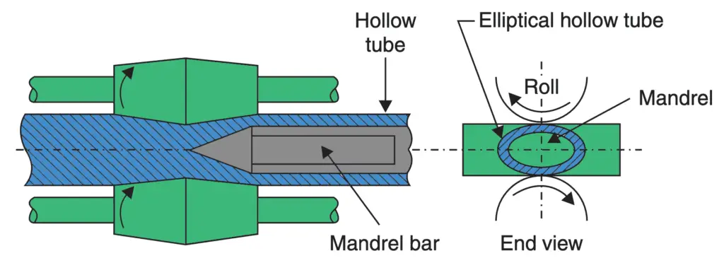
- In this process, a heated round billet with its leading end, in the centre of which a short guide hole has been punched or drilled, is pushed longitudinally between two large tapered rolls as shown in the following figure.

- The rolls revolve in the same direction and their axes are inclined at opposite angles of approx 6° from the axis of the billet.
- As the billet is caught by the rolls and is rotated, their inclination causes the material to be drawn forward.
- The small clearance between the rolls forces the material to deform into an elliptical shape.
- Due to compressive forces, secondary tensile stresses start acting in a direction perpendicular to the direction of the compressive stresses.
- The guide hole drilled/punched at the centre of the billet tears open.
- This action is assisted by a suitably placed mandrel.
- As the billet moves forward and keeps rotating the tearing action is propagated throughout the length of the billet.
- The result is a roughly formed seamless tube of elliptical cross-section.
- This roughly formed seamless tube is further rolled in a “plug rolling mill”.
- The final operations of “reeling” and “sizing” are further conducted on the cooling tubes to improve the size and finish tubes.
Conclusion
We have discussed the wire drawing process and the tube drawing and making of tubes with the schematic diagram. We have also discussed the other metal works such as the Extrusion, rolling, casting and Welding also. let us know what you think about this article in the comment section below.

Leave a Reply