In the previous article, we have discussed what are the different manufacturing processes. The manufacturing process turns the raw material into finished products. There are different manufacturing process which uses different technologies and machinery to get the final products from the raw material. In this article, we discussed the different casting processes.

Casting Processes
Casting is the oldest manufacturing process in which liquid molten metal is poured into the casting cavity. Allow the liquid metal to solidify to a defined shape, after solidification the defined casting metal is taken out by breaking the mould.
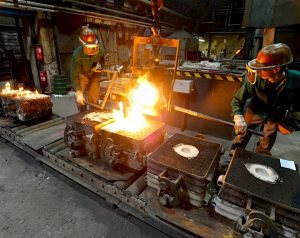
The sequence of steps involved in casting are
- Pattern making
- Mould and core making
- Pouring and solidification
- Fettling
- Inspection
1. Pattern Making
- The pattern is the replica of the casting to be made.
- The size of the pattern is slightly greater than the casting by an amount called allowances
- Pattern size = Casting ± Allowances
Allowances
- Shrinkage Allowance
- Machining Allowance
- Draft Allowance
- Shake Allowance
- Distortion Allowance
Different Types Of Patterns
Different types of patterns are used depending upon the designed casting, complexity of the shape, number of castings required, moulding process, surface finish and accuracy. They are as follows
- Solid or single piece pattern
- Split pattern
- Match plate pattern
- Gated pattern
- Sweep pattern
- Skelton pattern
- Loose piece pattern
- Follow board pattern
- Shell pattern
Let us discuss a few of these patterns in detail.
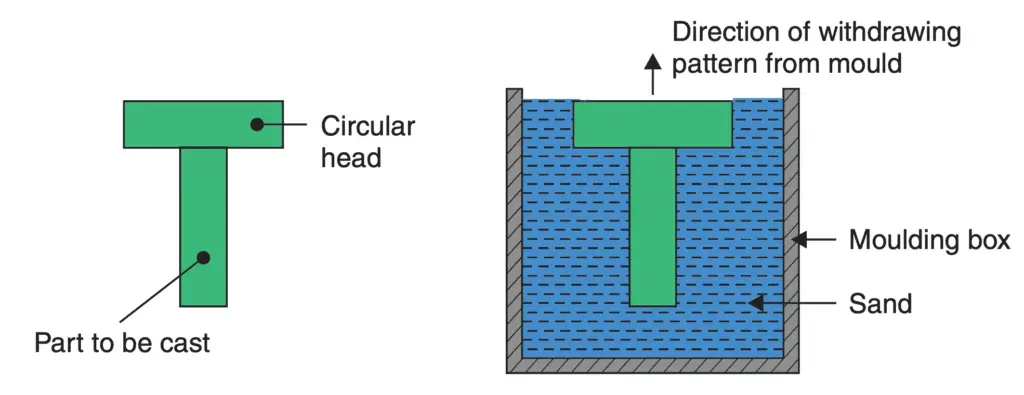
(i) Solid or single piece pattern: Such patterns are made in one piece and are suitable only for very simple castings. There is no provision for runners and risers etc. Moulding can be done either on the foundry floor (called pit moulding) or in a moulding box. There is no difficulty in withdrawing the pattern from the mould as the broadest portion of the pattern is at the top. As an example, if a cylindrical pin with a circular head has to be cast, a one-piece pattern shown in the following figure will be adequate.
(ii) Split pattern: It is not practical to have one piece pattern for parts of complicated shapes, because it would not be possible to withdraw the pattern from the mould. For example, if a circular head was added to the bottom of the pin shown in the above figure, it would make it necessary to go in for a split pattern as shown in the below figure.
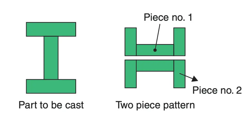
One-half of the impression in the mould will be made by using piece no. 1 in one moulding box and the other half of the impression will be made by using piece no. 2 in a second moulding box. After withdrawing the pattern halves from the respective moulding boxes, the two boxes will be assembled and clamped together, so that the complete impression is available for pouring the metal.
The two pattern halves are provided with locating dowels, so that one half may sit on the other half in the exact position required with no mismatch. Also, two tapped holes are provided on the flat mating surface of each part. These tapped holes are used to provide a grip to lift the pattern halves from the sand without damaging the mould impression.
The line along which the pattern is divided into halves is called the “parting line” and it usually follows the broadest cross-section of the casting. Deciding where the parting line should be is a matter of considerable skill and experience.
Some of the more complicated castings may require patterns to be split into three or even more pieces.
(iii) Loose piece pattern: In some cases, the casting may have small projections or overhanging
portions. These projections make it difficult to withdraw the pattern from the mould. Therefore these
projections are made as loose pieces. They are loosely attached to the main part of the pattern and the
mould is made in the usual way.
When the main pattern is withdrawn from the mould, the loose pieces slip off and remain behind
in the mould. After removing the main body of the pattern, the loose pieces are taken out first moving them laterally and then lifting them through the space vacated by the main pattern. The method is illustrated in the following figure.

(iv) Match plate pattern: Match plate is a metal plate, usually made of aluminium. The two halves of the split pattern are mounted on this matching plate one on either side. While fixing them to the match plate, care is taken so that there is no mismatch. These patterns are used in conjunction with mechanically operated moulding machines. The bottom side of the match plate pattern is used for making the bottom half of the mould impression in one moulding box (known as the drag). The upper side of the match plate pattern is used for making the mould impression in another moulding box. Finally, the two moulding boxes are kept on top of each other, the bottom box is known as the drag, whereas the top one is called the cope.
(v) Gated patterns: Sometimes along with the pattern for the casting, another portion is added so that when the impression is made in the moulding box, the cavity contains a shallow channel along with the main cavity for the object to be cast. This channel will be used for feeding molten metal into the main cavity and is known as the “gate”. Such patterns where provision for gating has been made are called gated patterns. It removes the necessity of making a gate separately.
(vi) Other pattern types include skeleton pattern, sweep pattern and segmental pattern etc. In these patterns, the full pattern is not made and the mould is completed with an improvised pattern. This is done to reduce the cost of pattern making. This procedure is resorted to if only one or two moulds are to be made.
Following are the different materials used for pattern making.
- Wood
- Plastic
- Metal
- Wax
- Mercury
2. Mould and core making
a) Mould Making
Mould making is the process of manufacturing by shaping liquid raw material using a rigid frame called a mould. Moulding sand will be used for manufacturing the mould. Consists of 3 basic elements
- Silica sand particles
- Clay
- Water or sodium silicate
This moulding sand basically follows the below properties
- Porosity property
- Strength
- Cohesiveness property
- Adhesiveness
- Refractoriness
- Collapsibility
- Flowability
Many methods are present for mould making. As follows
a) Hand Moulding
- Human hands are used for the force required for ramming or compressing the moulding sand is called hand moulding
- It is a cheaper methodology.
b) Machine moulding
Ramming or compressive force produced by the machine is called machine moulding. Processes are below:
- Jolting
- Squeezing
- Jolting and Squeezing
- Sand slinging
Read the full article about How a Mould is prepared for Casting Process?
b) Core Making
Whenever a hole, recess, undercut or internal cavity is required in casting, a core, which is usually made up of refractory material like sand is inserted at the required location in the mould cavity before finally closing the mould.
A core, being surrounded on all sides by molten metal, should be able to withstand high temperatures. It should also be adequately supported otherwise due to the buoyancy of molten metal, it will get displaced. When the molten metal around the core solidifies and shrinks, the core should give way, otherwise, the casting may crack (hot tear). As mentioned above that the Cores should be made of oil sand and dried in ovens before use.
Cores are made with the help of core boxes. Core boxes are made of wood and have a cavity cut in them, which is the shape and size of the core. The sand is mixed and filled in the core boxes. It is then rammed. A core box is made in two halves, each half contains the half impression of the core. Sometimes a core may need reinforcements to hold it together. The reinforcements are in the shape of wire or nails, which can be extracted from the hole in the casting along with core sand.
Core Prints
A core must be supported in the mould cavity. Wherever possible, this is done by providing core prints. Core prints are extensions of the core which rest in similar extensions of the mould cavity so that core remains supported in the mould cavity without the core falling to the bottom of the cavity.
For example, if the pin with collars shown in the following figure had a central hole, the hole could be produced by inserting a core in the mould cavity.

Another device to support cores is “chaplets”. These are clips made of thin sheets of the same metal as the casting. These clips are used to support the weight of cores. When the molten metal is poured, chaplets melt and merge into the molten metal.
This is used for making cavities and hollow projections which cannot normally produce by the pattern alone. Cores are normally made by CO2 moulding. Properties that core material should consist of are
- To avoid the bond formation between core and casting metal it should be non-metal.
- It should have high collapsibility.
- It should be moisture-free.
- It should have a high strength to withstand the self-weight and buoyancy force.
3. Pouring and solidification
a) Pouring Process
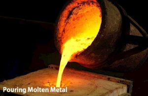
In this casting process to avoid oxidation, the molten metal is always poured into the casting cavity using a system called a gating system. It consists of mainly 4 basic elements
- Pouring basin
- Sprue
- Runner
- Ingate
Characteristics of idle gating system:
- The gating system must be designed such that time taken for pouring or filling of molten metal into the cavity should be as minimum as possible.
- This is to ensure that no part of casting cavity should start to solidify before complete filling of the cavity.
- The velocity of molten metal in gating system should be as high as possible within the limit of laminar flow.
- It should separate the impurities present in the molten metal.
Classification of the gating system
1. Based on pressure above the molten metal in the pouring basin.
- Non-pressurized gating system
- Pressurized gating system
2. Based on the position of in-gate
- Top gating system
- Bottom gating system
- Parting gating system
- Step gating system
Gating ratio = sprue area : runner area : in-gate area
b) Solidification Process
The heat transfer from molten metal to surroundings through the mould is considered an unsteady state of heat conduction with infinite wall thickness problem.
4. Fettling
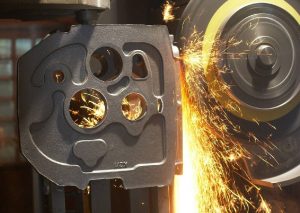
- The method used for breaking the mould and taking out casting from the mould is called a fettling operation.
- When the vibrations are applied to the mesh, the mould is getting broken slowly.
- The broken piece of the mould is falling into the pit leaving the mould boxes.
5. Inspection
a) Dimensional Inspection
In the casting process, the first casting will be inspected dimensionally and the pattern is qualified after that proceeds for the random inspection.
b) Defective Inspection
following are the different methods of inspection:
- Visual inspection
- Pressure test
- Magnetic particle inspection
- Dye penetrant inspection
- Radiographic Examination
- Ultrasonic Inspection
Different Casting Defects
Some of the common defects in the castings are described below:
- Blow-holes: They appear as small holes in the casting. They may be open to the surface or they may be below the surface of the casting. They are caused due to entrapped bubbles of gases. They may be caused by excessively hard ramming, improper venting, excessive moisture or lack of permeability in the sand.
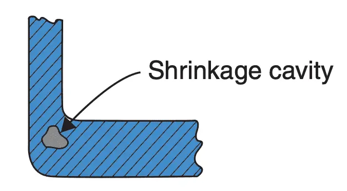
- Shrinkage cavity: Sometimes due to faulty design of casting consisting of very thick and thin sections, a shrinkage cavity may be caused at the junction of such sections. The shrinkage cavity is
totally internal. It is illustrated in the following figure. It is caused due to shrinkage of molten metal. The remedy is to use either a chill or relocation of risers.
- Misrun: This denotes incomplete filling of the mould cavity. It may be caused by bleeding of molten metal at the parting of cope and drag, inadequate metal supply or improper design of gating.
- Cold shut: A cold shut is formed within a casting when molten metal from two different streams meets without complete fusion. The low pouring temperature may be the primary cause of this defect.
- Mismatch: This defect takes place when the mould impression in the cope and drag do not sit exactly on one another but are shifted a little bit. This happens due to a mismatch of the split pattern
(dowel pin may have become loose) or due to defective clamping of cope and drag boxes. - Drop: This happens when a portion of the moulding sand falls into the molten metal. Loose sand inadequately rammed or lack of binder may cause this defect.
- Scab: This defect occurs when a portion of the face of a mould lifts or breaks down and the recess is filled up with molten metal.
- Hot tear: These cracks are caused in thin long sections of the casting if the part of the casting cannot shrink freely on cooling due to intervening sand being too tightly packed, which offers resistance to such shrinking. The tear or crack usually takes place when the part is red hot and has not developed full strength, hence the defect is called a “hot tear”. The reason may be excessively tight ramming of sand.
- Other defects include scars, blisters, sponginess (due to a mass of pinholes at one location)
and slag inclusions etc.
Different Types of Casting Process
- Shell moulding
- Investment casting process
- Die casting process
- Centrifugal casting process


It helps alot and well detailed
Welcome Sodiq