In metalworks, Rolling is the process of deforming metals or alloys to the required shape or thickness. Let us discuss more details on the Rolling of metal in production technology such as the mechanism used for Rolling, and some basic nomenclature used for rolling.

Rolling Process
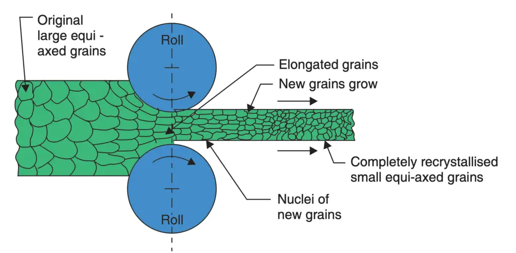
In this Rolling process, metals and alloys are plastically deformed into semifinished or finished products by being pressed between two rolls that are rotating. The metal is initially pushed into the space between two rolls, thereafter once the roll takes a ‘‘bit’’ into the edge of the material, the material gets pulled in by the friction between the surfaces of the rolls and the material.
When we feed the material to the Rolls, The material is subjected to high, compressive force as it is squeezed (and pulled along) by the rolls. This is a process to deal with the material in bulk in which the cross-section of material is reduced and its length increased. The final cross-section is determined by the impression cut in the roll surface through which the material passes and into which it is compressed. The essentials of the rolling process. This can be understood from the following figure.

Rolling can be done in both hot and cold conditions. In a rolling mill attached to a steel plant, the starting point is cast ingot of steel which is broken down progressively into blooms, billets and slabs. The slabs are further hot rolled into plates, sheets, rods, bars, rails and other structural shapes like angles, channels etc. Conversion of steel into such commercially important sections is usually done in another rolling mill called a merchant mill.
Rolling is a very convenient and economical way of producing commercially important sections. In the case of steel, about three-fourths of all steel produced in the country is ultimately sold as a rolled product and the remaining is used as forgings, extruded products and in cast form. This shows the importance of the rolling process.
Nomenclature of Rolled Products
The following nomenclature is in common usage for the Rolling products:
(i) Blooms: It is the first product obtained from the breakdown of Ingots. Abloom has a cross-section ranging in size from 150 mm square to 250 mm square or sometimes 250 × 300 mm rectangle.
(ii) Billet: A billet is the next product rolled from a bloom. Billets vary from 50 mm square to 125 mm square.
(iii) Slab: Slab is of rectangular cross-section with thickness ranging from 50 to 150 mm and is available in lengths up to 1 1/2 metres.
(iv) Plate: A plate is generally 5 mm or thicker and is 1.0 or 1.25 metres in width and 2.5 metres in length.
(v) Sheet: A sheet is up to 4 mm thick and is available in the same width and length as a plate.
(vi) Flat: Flats are available in various thicknesses and widths and are long strips of material of specified cross-section.
(vii) Foil: It is a very thin sheet.
(viii) Bar: Bars are usually of circular cross-section and of several metres in length. They are common stock (raw material) for capstan and turret lathes.
(ix) Wire: A wire is a length (usually in coil form) of a small round section; the diameter of which specifies the size of the wire.
Mechanism Of Rolling
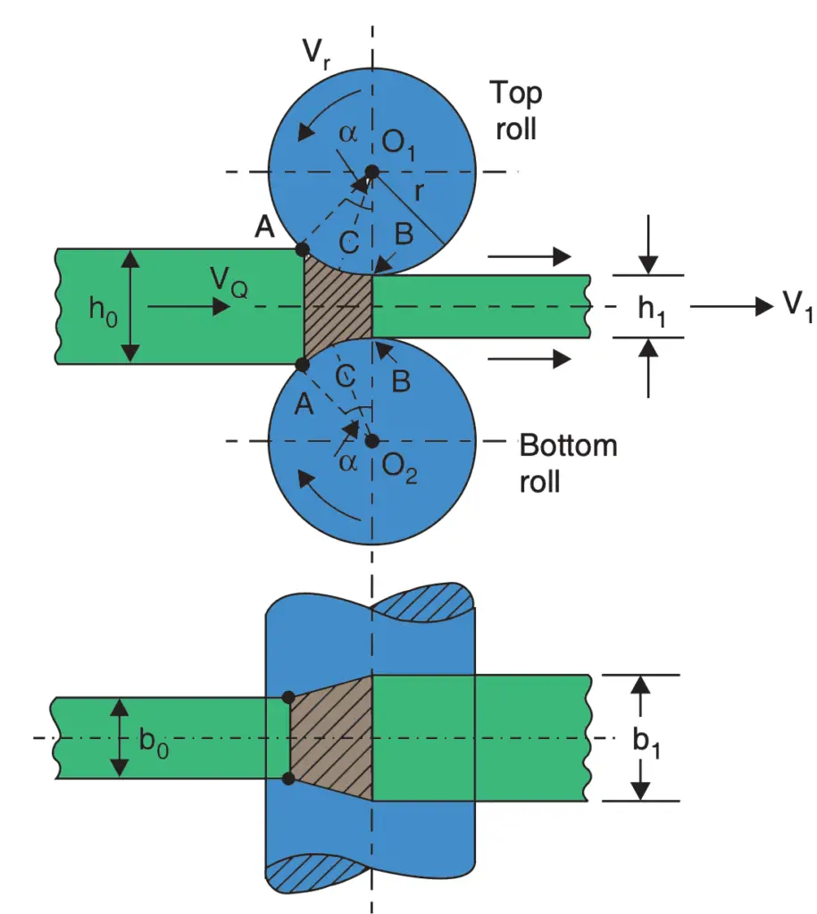
Refer to the following image.

Each of the two rolls contacts the metal surface along the arc AB, which is called arc of contact.
Arc AB divided by the radius of rolls will give an angle of contact (α). The rollers pull the material forwards only due to the friction existing between the roll surface and the metal.

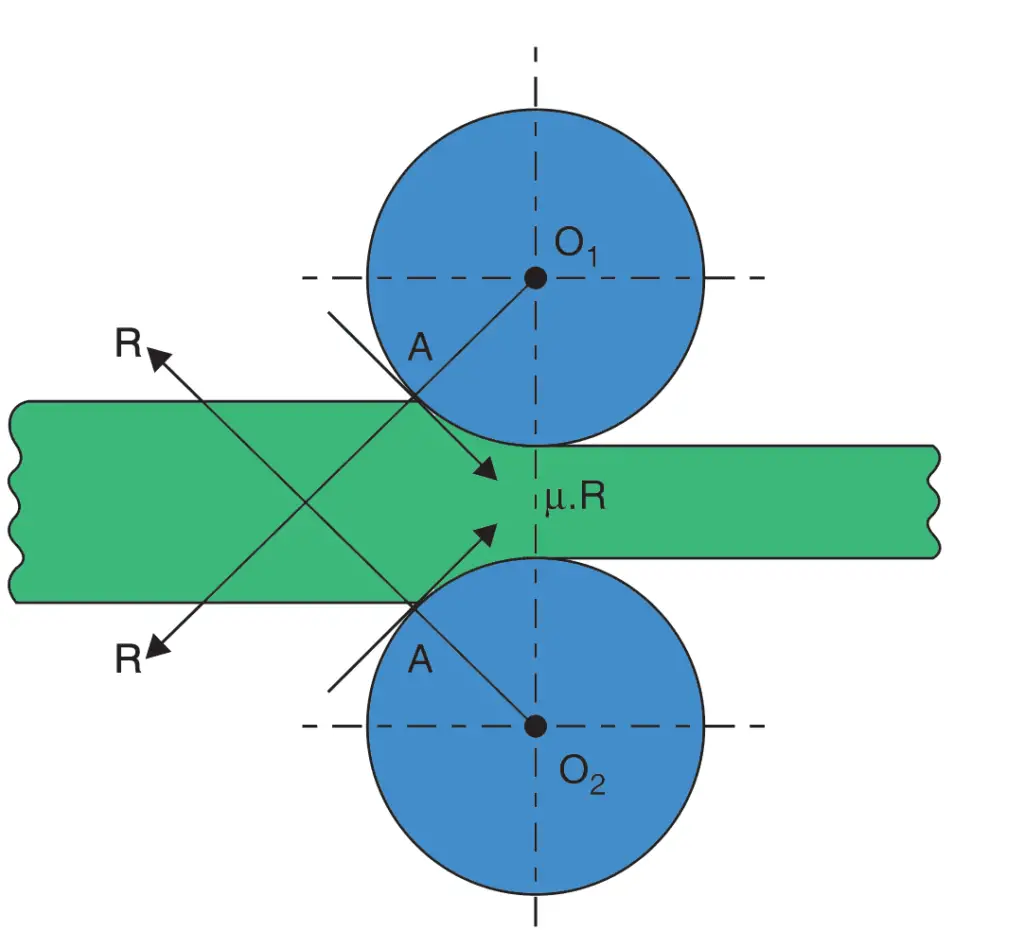
At the moment of the bite, the reaction at the contact point A will be R acting along radial line O1A and frictional force will be acting along tangent at A at right angles to O1A. In the limiting case,
R sin α = μR cos α
μ = tan α
α = tan–1 μ
If α is greater than tan–1 μ, the material would not enter the rolls unaided.
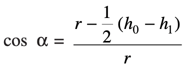
As will be seen,

Where
h0 is the thickness of the material
h1 is the gap between the two rollers at the narrowest point
r is the radius of the rollers
For a given diameter of rollers and the gap between them the value of h0 is limited by the value of μ which in turn depends upon the material of rolls and job being rolled, the roughness of their surfaces and the rolling temperature and speed.
In the case of hot rolling when maximum reduction is cross-section per pass is aimed, it may be necessary to artificially increase the value of μ by ‘‘ragging’’ the surface of rolls.
Ragging means making the surface of rolls rough by making fine grooves on the roll surface.
However, in cold rolling which is a finishing operation and cross-section reduction is limited, ragging of rolls is neither required nor desirable. In fact, in that case, some lubrication is resorted to in addition to giving a fine finish to the rolls
Another reason for making do with a lower coefficient of friction in cold rolling is that in this process, very high pressures are used and even with a low value of μ, adequate frictional force becomes available.
The usual values of biting angles employed in the industry are:
2–10° … for cold rolling of sheets and strips
15–20° … for hot rolling of sheets and strips
24–30° … for hot rolling of heavy billets and blooms
Rolling Procedure
In the rolling process, although the material is being squeezed between two rolls, the width (b0) of the material does not increase or increases only very slightly.
- Since the volume of material entering the rolls is equal to the volume of material leaving the rolls, and the thickness of material reduces from h0 to h1, the velocity of material leaving the rolls must be higher than the velocity of material entering the rolls.
- The rolls are moving at a uniform RPM. and their surface speed remains constant.
- The rolls are trying to carry the material into the rolls with the help of friction alone, there is no positive grip between the rolls and the material.
- On one side, therefore, i.e., point A where contact between the rolls and work material starts, the rolls are moving at a faster surface speed than the work material.
- As the material gets squeezed and passes through the rollers, its speed gradually increases and at a certain section CC as shown in the above figure called neutral or no-slip section, the velocity of metal equals the velocity of rolls.
- As the material is squeezed further, its speed exceeds the speed of the rolls.
- The angle subtended at the centre of the roll at the neutral section is called the angle of no-slip or critical angle (angle BO1C).
- The deformation zone to the left of the neutral section is called the lagging zone and the deformation zone to the right of the neutral section is termed the leading zone.
- If Vr is the velocity of roll surface, V0 the velocity of material at the entrance to the deformation zone and V1 at the exit of the rolls, we have
Forward slip = [(V1– Vr)/ Vr ]× 100 per cent,
Backward slip = [(Vr– V0)/Vr] × 100 per cent
The value of forwarding slip normally is 3–10% and increases with an increase in roll dia and coefficient of friction and also with a reduction in thickness of the material being rolled.
We have discussed different types of Rolling mills and difference between the Hot rolling and cold rolling here.
Some other useful terms associated with Rolling are explained below:
- Absolute draught Δh = (h0 – h1) mm,
- Relative draught = Δh/h0 × 100 per cent
- Absolute elongation, Δl = Final length – Original length of work material
- Coefficient of elongation = Final length/Original length
- Absolute spread = Final width of work material – Original width of material
Note: During cold working absolute spread may be taken as nil.
Conclusion
We have discussed what is Rolling in metalworks and described the rolling mechanism also discussed the Rolling procedure. We also have discussed different types of Rolling mills and difference between the Hot rolling and cold rolling here. Let us know what you think about this topic in the comment section below.

Leave a Reply