The Porter governor is a modification of Watt’s governor with an additional central load attached to the sleeve. In the previous article, we have discussed the Watt Governor in detail. The Watt governor is the simple centrifugal governor which works based on the balancing of the centrifugal force as the working principle. Now let’s discuss the Porter Governor in more detail.
Porter Governor
This Porter Governor is also a type of the Centrifugal Governor with an additional central load on the sleeve to increase the speed of the balls required to lift the sleeve on the spindle. Which will enable the governer to operate the mechanism to give necessary change in the fuel supply. So that we can use this Porter Governor for much more higher engine speeds than the watt Governor.
One of the disadvantage of the watt Governor is that, Due to the small height of the governer, and no additional load on the sleeve, at very much high speeds of the engine, the change in movement of sleeve on the spindle corresponds to the small variation in the speed is insufficient to make a governer to operate the mechanism to give necessary change in the fuel supply.
Construction and Working of Porter Governor
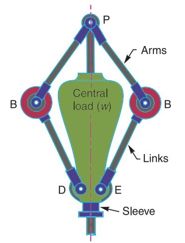
As you can see the above schematic diagram of the Porter Governor, it consists of two balls of equal mass, which are attached to the arms as shown above diagram. These balls got a name governor balls or the fly balls.
- These balls will be revolving around the spindle which is driven by the engine.
- As you can see the above schematic diagram of a porter governor, there are links joined to a sleeve where it can translate on the spindle freely.
- A central load of W is added on the sleeve to increase the revolution speed of the balls required to lift the sleeve on the spindle.
- A bell crank lever is connected to the sleeve and the other end of it will be connected to throttle valve located in the fuel supply passage.
- As the engine working, these balls also revolving around the spindle at a certain speed and maintained at a mean position radially with the speed of the engine due to the centrifugal force.
- Whenever there is a decrease in the engine speed due to the load, then the speed of the balls also changes and due to the less centrifugal force outwards, the balls revolve bit lower their means radial position.
- Then the sleeve connected by the links will automatically move downwards on the spindle, the bell crank lever opens the throttle valve to pass the more amount of fuel. So that the engine speed will be increased to its mean speed.
This is how the Porter Governer works to govern the fuel supply and regulates the mean speed of the engine when there is a variation in the load.
The movent of the sleeve on the spindle is a bit more sensitive when the engine is running at higher speeds due to the central load on the sleeve. This is an advantage of the porter Governor over the Watt Governor.
The height of the Porter Governor can be determined by the following formula
h = ((m+M)*895)/ m*N2 ( ∵ ω = 2 π N/60 , g = 9.81 m/s2 )
This is (m+M)/m times more than the watt governor heigh.
[m = Mass of the Balls, M = Mass of the cental load, N= speed of the balls]
Conclusion
We have discussed the Porter_governor, its construction and working principle along with the formula of porter governor to calculate the height of the spindle. If you have any further thoughts on this topic, let us know in the comment section below.
A Porter governor has arms 250 mm each and four rotating flyballs of mass 0.8 kg each. The sleeve
movement is restricted to ± 20 mm from the height when the mean speed is 100 r.p.m. Calculate the
central dead load and sensitivity of the governor neglecting friction when the flyball exerts a centrifugal
force of 9.81 N. Determine also the effort and power of the governor for 1 percent speed change.