Forging is a process of deforming the metals and alloys into desired and specific shapes by the application of repeated blows from a hammer. Forging can be done either while the metal or the alloy is hot condition or sometimes forging can be done when the metals are in cold condition. Let us discuss more details on the Forgings and the different types of forgings. We will discuss the defects of the forging components also.

As we mention that the forging is a deforming process of the raw metals or the alloys. The raw material used for the forging process is usually a piece of a round or square cross-section slightly larger in volume than the volume of the finished component. Depending on the end-use of the component, the forged part may be used as such or (more frequently) it has to be machined to the correct size to close tolerances. The initial volume of material taken must, therefore, allow for loss due to scaling and the machining allowance.
Classification Of Forging
Forging is done by hand or with the help of power hammers. Sometimes hydraulic presses are also used
for forging.
- Hand Forging
- Upsetting
- Drawing Down
- Cutting
- Bending
- Punching and Drifting
- Setting Down and finishing
- Forge Welding
- Forging with Power Hammering
- Spring Hammer
- Pneumatic power hammer
- Steam Hammer
- Die Forging with Power Hammering
- Open Die Forging
- Impression Die Forging
- Closed Die Forging
- Drop Stamping or Drop Forging Hammers
- Forging Presses
- Machine Forging
1. Hand Forging
Under the action of the compressive forces due to hammer blows, the material spreads laterally i.e., in a direction at right angles to the direction of hammer blows. Obviously brittle material like cast iron cannot be forged as it will develop cracks under the blows from a hammer.
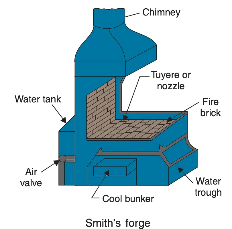
An ordinary blacksmith uses an open-hearth using coke (or sometimes steam coal) as fuel for heating the metal and when it has become red-hot, the blacksmith’s assistant (called striker on hammerman) uses a handheld hammer to deliver blows on the metal piece while the blacksmith holds it on an anvil and manipulates the metal piece with a pair of tongs. This type of forging is called “hand forging” and is suitable only for small forgings and small quantity production.
A blacksmith’s hearth, ancillary equipment and tools used by the blacksmith are shown below.
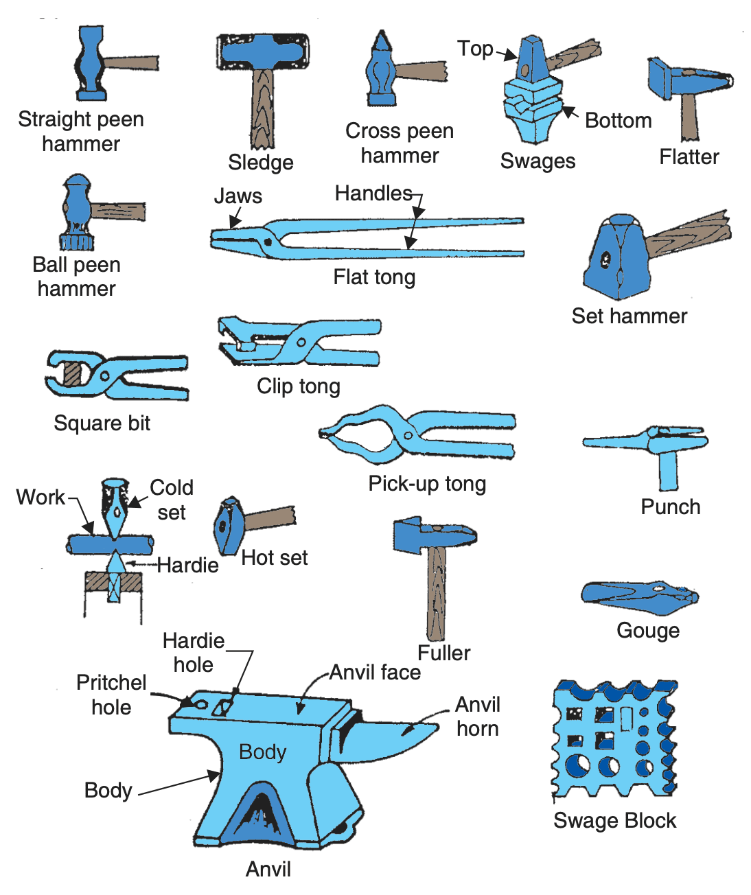
Basic forging operations employed in giving the required shape to the workpiece are described below:
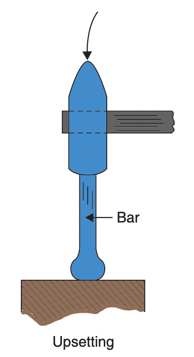
(i) Upsetting: It is the process of increasing the cross-section at expense of the length of the workpiece.
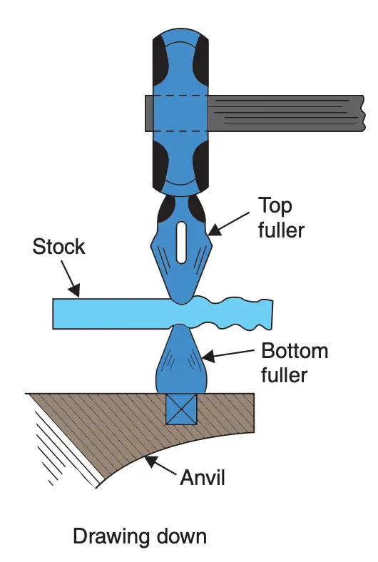
(ii) Drawing down: It is the reverse of the upsetting process. In this process, length is increased and
the cross-sectional area is reduced.
(iii) Cutting: This operation is done by means of hot chisels and consists of removing extra, metal from the job before finishing it.
(iv) Bending: Bending of bars, flats and other such material is often done by a blacksmith. For making a bend, first, the portion at the bend location is heated and jumped (upset) on the outward surface. This provides extra material so that after bending, the cross-section at the bend does not reduce due to elongation.
(v) Punching and drifting: Punching means an operation in which a punch is forced through the workpiece to produce a rough hole. The job is heated, kept on the anvil and a punch of suitable size is forced to about half the depth of the job by hammering. The job is then turned upside down and punch is forced in from the other side, this time through and through.
Punching is usually followed by drifting i.e, forcing a drift in the punched hole through and through. This produces a better hole as regards its size and finish.
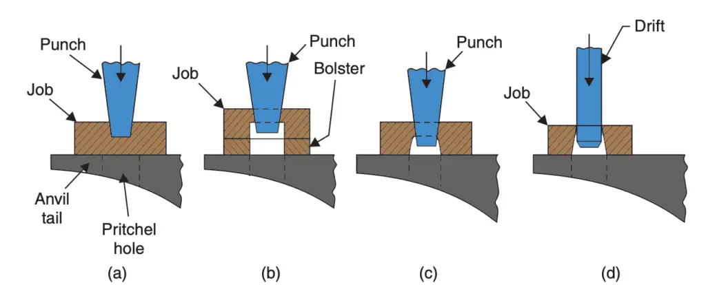
(b) Job turned upside down, being punched through using a bolster
(c) Job turned upside down, being punched through using Pritchel hole
(d) Operation of drifting
(vi) Setting down and finishing: Setting down is the operation by which the rounding of a corner is removed to make it a square. It is done with the help of a set hammer. Finishing is the operation where the uneven surface of the forging is smoothened out with the use of flatter or set hammer and round stems are finished to size with the use of swages after the job has been roughly brought to desired shape and size.
(vii) Forge welding: Sometimes, it may become necessary to join two pieces of metal. Forge welding of steel is quite common and consists of heating the two ends to be joined to white heat (1050°C – 1150°C). Then the two ends of steel are brought together having previously been given a slightly convex shape to the surfaces under joining. The surfaces are cleaned of scale. They are then hammered together using borax as flux. The hammering is started from the centre of the convex surface and progresses to the ends. This results in the slag being squeezed out of the joint.
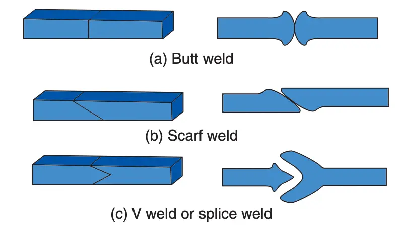
Hammering is continued till a sound joint is produced. Several types of joints can be made viz., butt joint, scarf joint or splice joint.
2. Forging with Power Hammers
The use of hand forging is restricted to small forgings only. When a large forging is required, comparatively light blows from a hand hammer or a sledgehammer wielded by the striker will not be sufficient to cause significant plastic flow of the material. It is, therefore, necessary to use more powerful hammers. Various kinds of power hammers powered by electricity, steam and compressed air (i.e., pneumatic) have been used for forging. let us discuss these hammers briefly.
a. Spring hammer
It is a light hammer powered by an electric motor and gives repeated blows when it is operated by a foot-operated treadle. This type of hammer is now obsolete and was best suited for small forgings. Though various designs of this hammer were in use, a typical spring hammer is shown below.
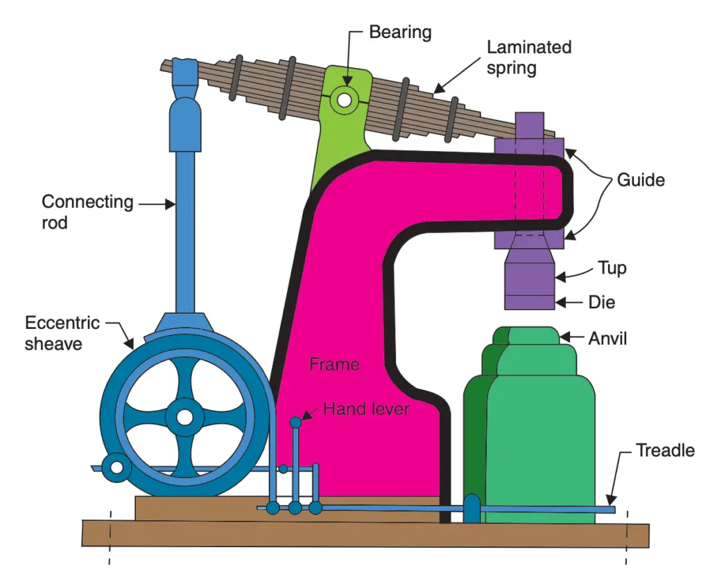
Construction of Spring Hammer
- In this design, an electric motor rotates a pair of pulleys, a loose and another fast pulley.
- The loose pulley rotates idly on its shaft.
- The fast pulley is fastened on its shaft by means of a key so that when the fast pulley rotates, it rotates the shaft as well.
- The shaft carries an eccentric sheave on it with the result that when the electric motor rotates the fast pulley, the eccentric sheave also rotates with it and imparts vertical reciprocatory motion to the connecting rod.
- This upper end of the connecting rod is connected to one end of a laminated bearing spring.
- The other end of this spring is connected to a ram which can slide up and down in a vertical guide provided in the machine frame at the front of the machine.
- To this ram, a tup (and a die, if required) is fitted. Also resting vertically below the ram and tup is an anvil resting on a base.
Operation of Spring Hammer
The electric motor is normally connected to the loose pulley, but when the hammer operator depresses the treadle with his foot, the motor gets connected to the fast pulley and when the connecting rod moves up, the front end of the spring moves down, the spring buckle in the centre of the spring being pivoted. When the connecting rod moves down, the ram moves up. Thus rotation of motor causes up and down motion of ram and tup which is used for hammering the workpiece kept on the anvil.
Usually, there is an arrangement for shifting the position of the pivot. If the pivot is shifted towards the connecting rod, the vertical movement of ram and tup increases and so does the severity of the hammering action. When the pressure of the foot is removed from the treadle, the motor gets connected to the loose pulley and a brake applies automatically stopping the hammering action instantly. Spring hammers were made in various capacities with tups weighing from 30 to 250 kg and having a capability of running up to 300 blows per minute.
b. Pneumatic Power Hammers
A typical form of the pneumatic hammers is shown below.
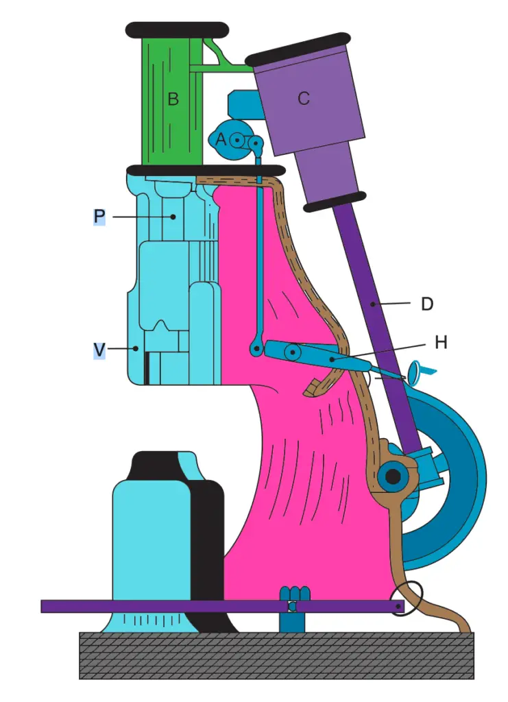
- An electric motor rotates a crank which in turn moves a connecting rod (D) to and fro i.e., the rotary motion of the crank is converted into a reciprocating motion.
- This reciprocating motion is delivered to a piston working inside cylinder ‘C’.
- The cylinder and piston assembly are provided with suitable air inlet ports so that the entire assembly acts as a reciprocating air compressor.
- The compressed air can be delivered to another cylinder piston assembly B, through air-valve A.
- This air valve A is operated by the hammerman of the person operating the hammer by means of the handle shown H in the figure.
- When the air valve A is fully closed, it disconnects the supply of air to cylinder B and the piston of cylinder B rests in the bottom position.
- At this juncture, the tup attached to the piston through a piston rod (P) rests on the anvil.
- However, when the air valve ‘A’ is opened, the air compressed in cylinder C is delivered to cylinder B, which is a double-acting cylinder.
- The compressed air first enters below the piston lifting the piston up and then it enters above the piston forcing it downwards with great force.
- This upward and downward motion of the piston in cylinder B is delivered to the tup which moves in a vertical guide V provided in the frame of the power hammer and the tup strikes the workpiece kept on the anvil below it.
By regulating the opening of air valve A, the severity of the blows can be controlled from very light to very heavy. The capacity of the hammer is characterised by the weight of moving parts including the tup in-cylinder B. Pneumatic hammers are available in capacities varying from a quarter of a ton to five tonnes.
(c) Steam Hammers
These hammers differ from the pneumatic hammer described above in that for raising steam, a separate boiler is required. Thus in a steam hammer, cylinder ‘C’ of the pneumatic hammer is not required. The piston in cylinder B is powered by the steam drawn from the boiler and operated by a simple slide valve mechanism. The cylinder B is double-acting and since the steam pressure is higher than the air pressure in pneumatic hammers, the striking force in steam hammers is higher than for the similar size of the pneumatic hammers.
3. Die Forging With Power Hammers
The tools used for power hammers are similar in shape to the tools used in hand forging but are larger and more robust. As far as possible, the effort is made to finish the shape required in one heat only. Usually, the bottom surface of the tup and the top of the anvil are flat as in the case of hand forging, but to increase production and cut down cost, dies are often used. The top die is fastened securely to the tup and the bottom die is fitted securely on the anvil. One half of the impression of the finished job is sunk in the top die, while in the bottom die, the other half of the impression is sunk. The correct volume of raw material is heated in the furnace and a rough shape is first given to it. Thereafter it is placed on the bottom die and blows are given with the tup and top die. The material spreads to fill all the vacant space in the impressions sunk in the dies. Such a method of forging is called die forging.
As we have alredy mentioned above there are three types of die forging methods are prevalent. Those are
(a) Open die forging
(b) Impression die forging
(c) Closed die forging
(d) Drop Stamping Or Drop Forging Hammers
(a) Open Die Forging
In this type of forging, the metal is never completely enclosed or confined on all sides. Most open dies
forgings are produced on flat, V or swaging dies. Swaging dies are usually round but may also be of other shapes e.g., double V. This has been illustrated in the following schematic.

The common “upsetting” operation done on a hammer can also be considered as an example of open die forging with two flat dies as shown in the below figure.
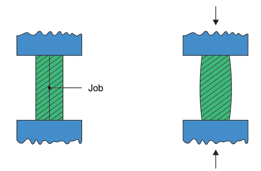
Advantages claimed for open die forging are
(i) Simple to understand and operate
(ii) Inexpensive tooling and equipment as no die-sinking is involved and
(iii) a Wide range of workpiece sizes can be accommodated.
The main disadvantage is a low volume of production and difficulty in close size control.
(b) Impression Die Forging
Here half the impression of the finished forging is sunk or made in the top die and another half of the impression is sunk in the bottom die. The process of cutting the impression in a die is called die-sinking and is performed on a special kind of machine called die sinking machine.
In impression die forging, the workpiece is pressed between the dies. As the metal spreads to fill up the cavities sunk in the dies, the requisite shape is formed between the closing dies. Some material that is forced out of the dies, is called “flash”. The flash provides some cushioning for the dies, as the tup strikes the anvil.
The flash around the workpiece is cut and discarded as scrap. For a good forging, the impression in the dies has to be completely filled by the material. This may require several blows of the hammer, a single blow may not be sufficient. To facilitate the production of good forgings, the workpiece may be given a rough shape by hand forging before dying forging is done.
(c) Closed Die Forging
Closed die forging is very similar to impression die forging, but in truly closed die forging, the amount of material initially taken is very carefully controlled, so that no flash is formed. Otherwise, the process is similar to impression die forging. It is a technique that is suitable for mass production.
(d) Drop Stamping Or Drop Forging Hammers
Very often, for closed die or impression die forging, a modified version of the power hammer is used. It is called a drop stamping or drop forging hammer and gives better results. In this case, the tup is not an ancient integral part of the piston and the piston rod assembly but is separate. The tup, to which the upper half of the die is fixed is lifted by means of flexible ropes or a flexible canvas belting. It is then dropped onto the anvil to which the lower half of the dying is attached. Its downward movement is gravity controlled free fall guided by the vertical guides provided in the frame of the hammer. The flexible ropes ensure, that after striking the anvil, the tup is free to rebound. Usually, one fall of the tup may complete the forging. The metal piece is given a rough shape before being drop stamped.
4. Forging Presses
Occasionally, high capacity hydraulic presses are used for forging and the metal is shaped by the squeezing action of the press rather than the hammering action of the hammer. Closed dies are used with impressions sunk in both die, the upper die is fixed on the ram and the lower die is fastened to the platen of the press. Presses are usually of a vertical configuration. Presses produce forgings of superior structural quality.
5. Machine Forging
For specific jobs like mass manufacture of bolts and nuts from bar stock, special forging machines have been developed. These machines work alongside a furnace in which one end of the bar is heated for some length. The heated end of the bar is then fed into the machine. With the help of dies and a heading tool, the hexagonal head of the bolt is forged by “upsetting”. These machines are in reality horizontal mechanical presses that can be operated by a foot pedal. The die consists of two halves and a heading tool. The sequence of operations can be understood from below figure.
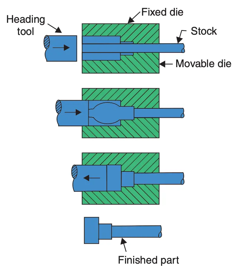
After the bolt head is forged, the bolt of the required length can be had by shearing the bar at an appropriate place. The bar is then again inserted into the furnace for heating and the whole process is repeated.
Forging Defects
The common forging defects can be traced to defects in raw material, improper heating of the material,
faulty design of dies and improper forging practice.
The Most common defects present in forgings are:
- Laps and Cracks at corners or surfaces lap is caused due to following a layer of material over another surface. These defects are caused by improper forging and faulty die design.
- Incomplete forging – either due to less material or inadequate or improper flow of material.
- Mismatched forging due to improperly aligned die halves.
- Scale pits – due to squeezing of scales into the metal surface during hammering action.
- Burnt or overheated metal – due to improper heating.
- Internal cracks in the forging are caused by the use of heavy hammer blows and improperly heated and soaked material.
- Fibre flow lines disruption due to the very rapid plastic flow of metal.
Heat Treatment of Forgings
The forged components may be subjected to severe stresses in service. To improve service life, to improve properties, to remove internal stresses and sometimes to improve the machinability, forgings may be given a suitable heat treatment after completing forging operations. The most common heat treatment given is normalising.
Cold Forging
Limited formability at room temperature restricts the use of cold forging to low and medium carbon steels and for products where not much deformation is required to obtain the final form. Usually, the stock is in the form of wire or thin rods at one end of which ahead is formed in a cold upsetting operation. Usually, a mechanical press is used. Some typical products include nails, small diameter rivets pins, brass bolts etc.
Conclusion
We have discussed all the different types of Hot forging types along with the some of the Forging defects and also discussed the heat treatment of the Forging. let us know what do you think about this article in the comment sectiion below.

Sundar, you wrote an interesting post! Forging is the process of shaping metal pieces/plates by hammering, pressing, or rolling them. This is given by a hammer, press, or die. It is simply the skill of heating and shaping hot metal to create a form or shape suitable for a particular purpose or usage. Forging is vital in the creation of various products that are essential to goods manufacturing and industrial activities.