A Cotter joint is a joint which is locked by a cotter. A cotter is a flat wedge-shaped piece of rectangular cross-section and its width is tapered from one end to another for an easy adjustment. Mostly it is tapered on one side but sometimes it may be tapered on both sides. Let us see the different types of the Cotter Joint and the applications.
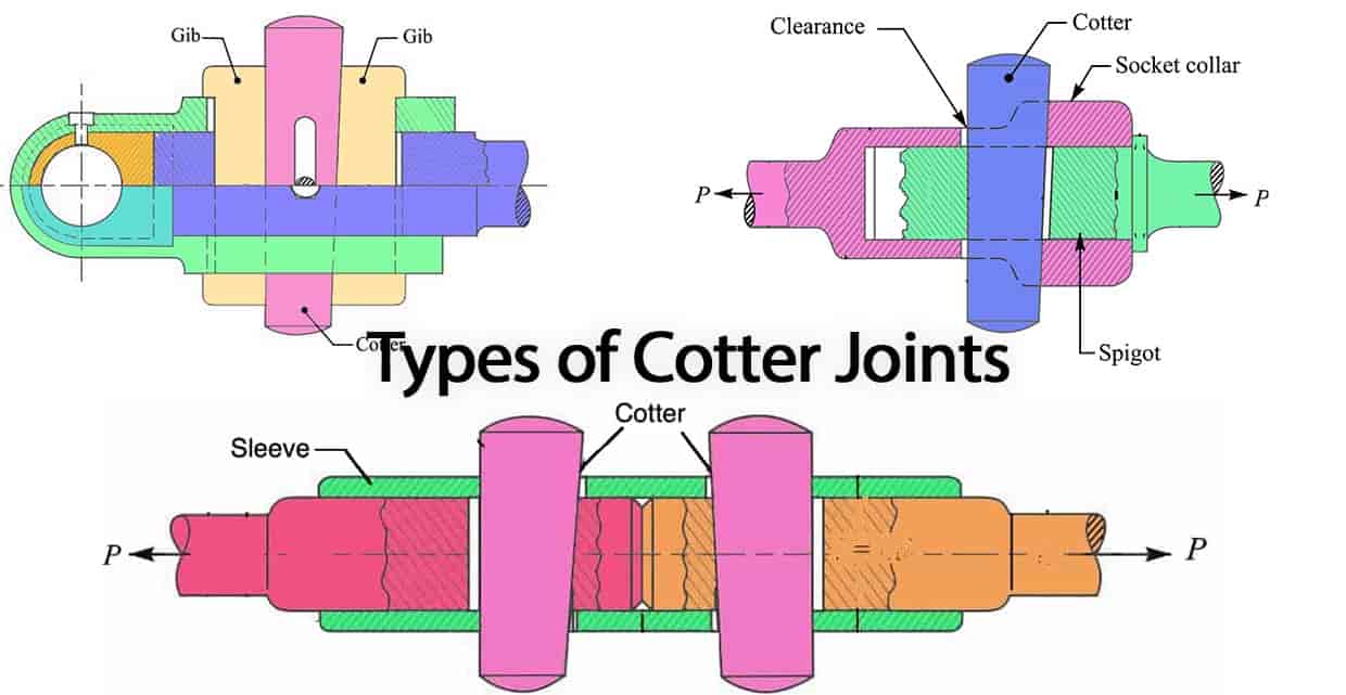
Cotter Joint
As we mention that the Cotter is the key element for that Cotter joint make a temporary joint allows us to disassemble the joint whenever it is necessary.
- A Typical Cotter has a taper that varies from 1 in 48 to 1 in 24 and it may be increased up to 1 in 8, if a locking device is provided.
- In order to lock the cotter in place we need additional locking device such as a taper pin or a set screw on the lower end of the cotter to keep in its place.
- The cotter is usually made of mild steel or wrought iron.
- The cotter joint comes under the temporary fastening method.
- Cotter Joints are used to connect rigidly two co-axial rods or bars which are subjected to axial tensile or compressive forces.
- This cotter joints can be fount in well know applications such as in
- Connecting a piston rod to the cross-head of a reciprocating steam engine,
- Connecting a piston rod and its extension as a tail or pump rod,
- in strap end of connecting rod
Types Of Cotter Joint
There are 3 types of cotter joint.
Let us discuss these cotter joints in detail.
1. Socket and Spigot Cotter Joint
The following image represents the socket and spigot Cotter Joint.
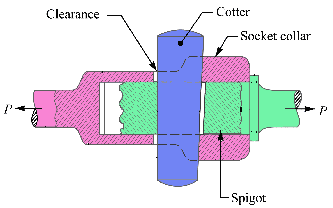
- In the above socket and spigot cotter joint, one end of the rods is provided with a socket type of end as shown as and the other end of the other rod is inserted into a socket.
- The end of the rod which goes into a socket is also called a spigot.
- A rectangular hole is made in the socket and spigot.
- A cotter is then driven tightly through a hole in order to make the temporary connection between the two rods.
- The load is usually acting axially, but it changes its direction, and hence the cotter joint must be designed to carry both the tensile and compressive loads.
- The compressive load is taken up by the collar on the spigot.
Read more How to design the Socket and Spigot Cotter Joint.
2. Sleeve and Cotter Joint
Following is the Sleeve and Cotter Joint schematic diagram with the parameters.

As we have seen above, the sleeve and cotter joint is used to connect two round rods or bars.
- In this type of joint, a sleeve also called as muff is used over the two rods and then two cotters (one on each rod end) are inserted in the holes provided for them in the sleeve and rods.
- The Sleeve and cotter is usually have a taper of 1 in 24. It may be noted that the taper sides of the two cotters should face each other as shown in above schematic diagram.
- The clearance is so adjusted that when the cotters are driven in, the two rods come closer to each other thus making the joint tight.
Read more about how to design the Sleeve and Cotter Joint.
3. Gib and Cotter Joint
A gib is a piece of mild steel having the same thickness and taper as the cotter. A gib and cotter joint is usually used in the strap end (or big end) of a connecting rod as shown below figure.
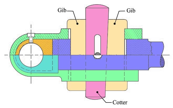
For the cotter joint, we have a possibility that we do not need to use the gib. In such cases, when the cotter alone is used, the friction between its ends and the inside of the slots in the strap tends to cause the sides of the strap to spring open outwards as shown dotted in the below figure.
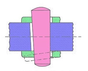
We have to prevent this, so we have to use Gibs. So what if we have used Gib as shown below. Either we can use one Gib or two Gibs on both sides which hold together the ends of the strap.
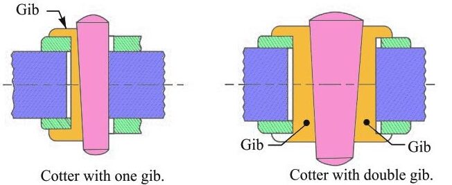
Moreover, gibs provide a larger bearing surface for the cotter to slide on, and it also increases the holding power. Thus, the tendency of cotter to slacken back owing to friction is considerably decreased. The Gib, also, enables parallel holes to be used.
When one gib is used, the cotter with one side tapered is provided and the gib is always on the outside.
When two jibs are used, the cotter with both sides tapered is provided.
Sometimes to prevent loosening of the cotter, a small set screw is used through the rod jamming against the cotter.
Read more about how to design the Gib and Cotter Joint for Connecting rod.
Applications of Cotter Joints
- Historically, the Cottar joint has been used to connect connecting rods to steam engines and pumps used in dumping mines.
- Cotter Joints are used between the piston rod and the tail of the pump rod.
- Cotter’s joints are used between the slide spindle and the fork of the valve mechanism.
- Cotter and Dowell arrange to join two parts of a flywheel.
- Foundation bolt: mainly used for fastening foundation and construction heavy machines
- In an automobile engine, the cotter joint is used to connect the extension of the piston rod with the connecting rod in the crosshead.
- The Cottar joint has historically been used to connect connecting rods to steam engines and pumps of dumping mines.
- It is used in bicycles to connect the paddle to the sprocket wheel.
- Use a wet air pump to join a tail rod with the piston rod.
- It is used to connects two rods of equal diameter subjected to axial forces.
Conclusion: We have discussed the 3 different types of Cotter Joint and the applications of the cotter joint. Also, we have derived the relations for the design parameters of these Cotter joints in the individual articles,. Please following the links mentions above to learn more about the design of cotter joints.

Leave a Reply