A brake is a device by means of which artificial frictional resistance is applied to a moving machine member, in order to retard or stop the motion of a machine. In the process of performing this function, the brake absorbs either the kinetic energy of the moving member or potential energy given up by objects being lowered by hoists, elevators, etc. In the previous articles, we discussed how we can calculate the energy absorbed by a brake and Heat Dissipation during Braking. We also discussed the different types of Brakes in the previous article. Let us discuss the Simple Band Brake in detail.
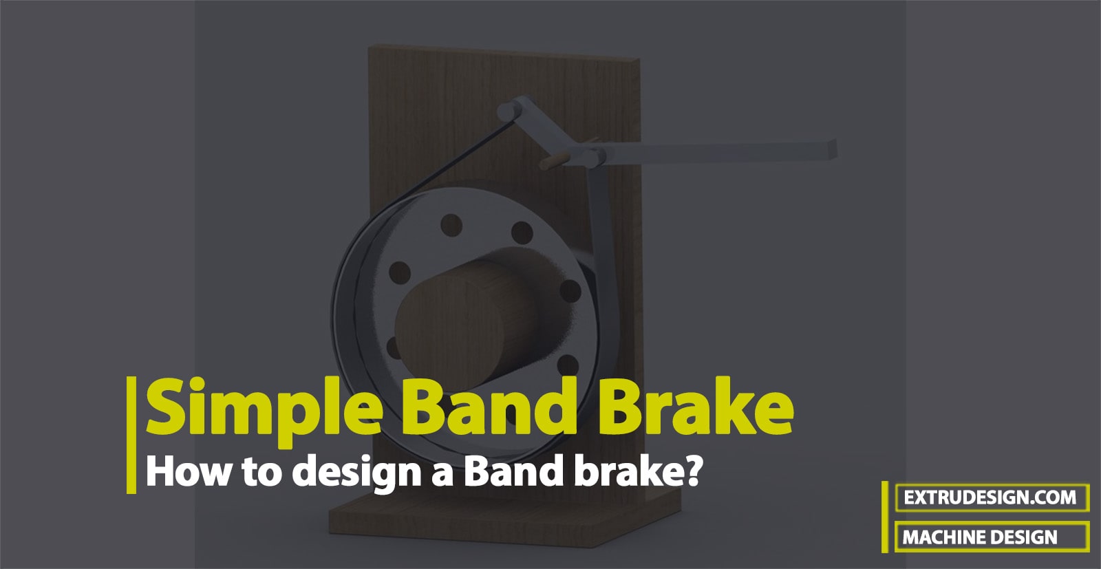
As we mentioned above that the brake is used to retard or stop the motion of a machine. This action is called Braking. In the process of braking, the brake absorbs either the kinetic energy of the moving member or potential energy given up by objects being lowered by hoists, elevators etc. The energy absorbed by brakes is dissipated in the form of heat. This heat is dissipated in the surrounding air (or water which is circulated through the passages in the brake drum) so that excessive heating of the brake lining does not take place.
The design or capacity of a brake depends upon the following factors:
- The unit pressure between the braking surfaces
- The coefficient of friction between the braking surfaces
- The peripheral velocity of the brake drum
- The projected area of the friction surfaces
- The ability of the brake to dissipate heat is equivalent to the energy being absorbed.
The major functional difference between a clutch and a brake is that a clutch is used to keep the driving and driven member moving together, whereas brakes are used to stop a moving member or to control its speed.
We also solved an example problem to stop A vehicle of mass 1200 kg moving down the hill at a slope of 1:5. by finding how much amount of Braking Torque is required to stop the vehicle in the previous article.
Simple Band Brake
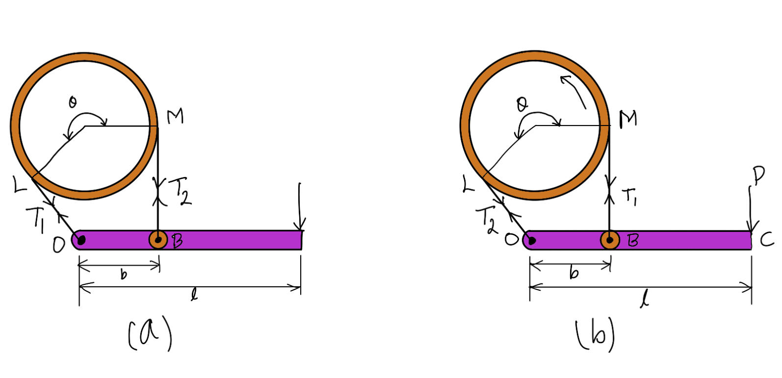
A band brake consists of a flexible band of leather, one or more ropes, or steel lined with friction material, which embraces a part of the circumference of the drum. A band brake, as shown in the following figure, is called a simple band brake in which one end of the band is attached to a fixed pin or fulcrum of the lever while the other end is attached to the lever at a distance b from the fulcrum.
When a force P is applied to the lever at C, the lever turns about the fulcrum pin O and tightens the band on the drum and hence the brakes are applied. The friction between the band and the drum provides the braking force. The force P on the lever at C may be determined as discussed below:
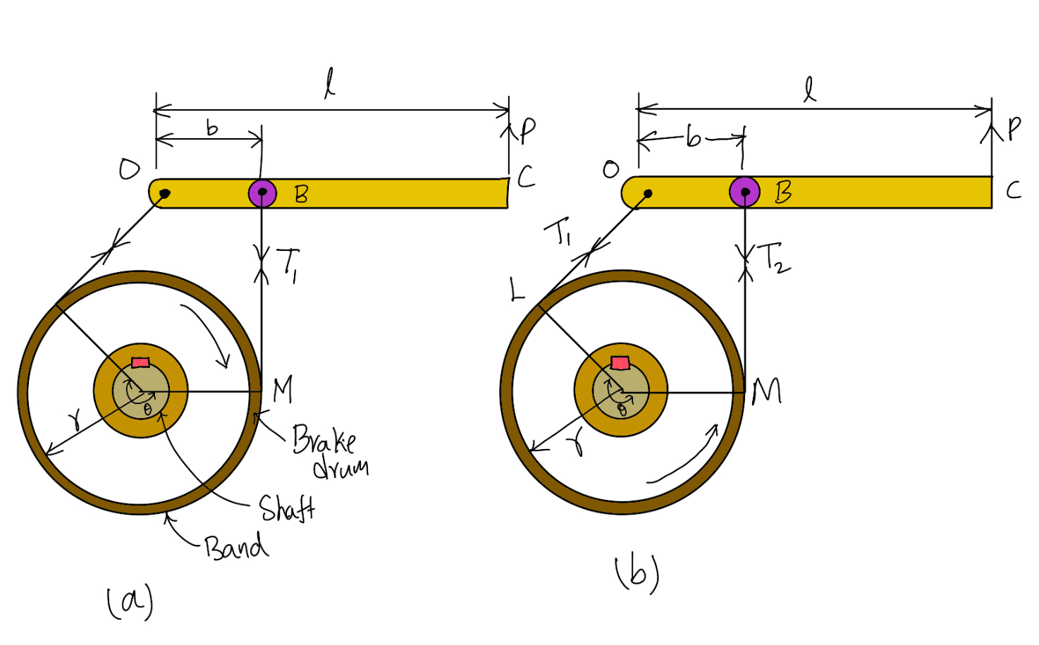
(a) Clockwise Rotation of Drum (b) Anticlockwise Rotation of Drum
Let
T1 = Tension in the right side of the band,
T2 = Tension in the slack side of the band,
θ = Angle of the lap (or embrace) of the band on the drum,
μ = Coefficient of friction between the band and the drum,
r = Radius of the drum,
t = Thickness of the band, and
re = Effective radius of the drum = r + t/2.
We know that limiting ratio of the tensions is given by the relation,
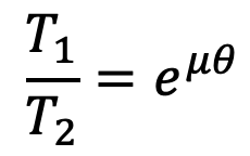
or
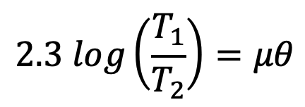
and braking force on the drum = T1 – T2
∴ Braking torque on the drum,
TB = (T1 – T2) r
….Neglecting the thickness of the band
TB = (T1 – T2) re
….Considering the thickness of the band
Now consider the equilibrium of the lever OBC. It may be noted that when the drum rotates in the clockwise direction as shown in the above figure (a), the end of the band attached to the fulcrum O will be slack with tension T2 and the end of the band attached to B will be tight with tension T1.
On the other hand, when the drum rotates in the anticlockwise direction as shown in the above figure (b), the tensions in the band will reverse, i.e. the end of the band attached to the fulcrum O will be tight with tension T1 and the end of the band attached to B will be slack with tension T2. Now taking moments about the fulcrum O, we have
P.l = T1.b
…(for clockwise rotation of the drum)
P.l = T2.b
…(for anticlockwise rotation of the drum)
where
l = Length of the lever from the fulcrum (OC)
b = Perpendicular distance from O to the line of action of T1 or T2
👉Important Notes:
1. When the brake band is attached to the lever, as shown in the above schematic figures (a) and (b), then the force (P) must act in the upward direction to tighten the band on the drum.
2. Sometimes the brake band is attached to the lever as shown in the following figures (a) and (b), then the force (P) must act in the downward direction to tighten the band. In this case, for clockwise rotation of the drum, the end of the band attached to the fulcrum O will be tight with tension T1 and a band of the band attached to B will be slack with tension T2. The tensions T1 and T2 will reverse for anticlockwise rotation of the drum.
(a) Clockwise Rotation of Drum (b) Anticlockwise Rotation of Drum
3. If the permissible tensile stress (σt) for the material of the band is known, then the maximum tension in the band is given by
T1 = σt × w × t
where
w = Width of the band
t = Thickness of the band
4. The width of the band (w) should not exceed 150 mm for drum diameter (d ) greater than 1 meter and 100 mm for drum diameter less than 1 meter. The band thickness (t) may also be obtained by using the empirical relation i.e. t = 0.005 d
For brakes of hand-operated winches, steel bands of the following sizes are usually used:
| Width of band (w) in mm | 25 – 40 | 40 – 60 | 80 | 100 | 140 – 200 |
| Thickness of band (t) in mm | 3 | 3 – 4 | 4 – 6 | 4 – 7 | 6 – 10 |

Leave a Reply