Sections in Creo: Drafting in Creo is quite good experience until we face a tough situation that we can not execute. Out of those things, Section in drafting is the one where most of the people will get irritated with the bunch of options available in creo. In this article, we have detailed about all the Sectioning option in creo.
Sections in Creo
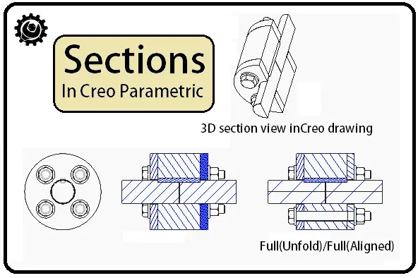
The Sectioning options in creo are Listed here!
- Planar Section
- Zone Section
- Offset section
- Full unfolded section
- Full aligned Section
- 3D section in Creo drawing
These are the pretty beautiful options in creo to make a section in the Drawings.
Sometimes In Creo drawings, it is necessary to include 3D sectional view or Offset sectional cut to include inside components in the cross-section. In this article, we will discuss the complete sections in Creo Parametric.
Watch this Video For Better Understanding. Or otherwise, Scroll Down for step by step process
Follow the slides for a quick overview
-
Planar Sections in Creo:

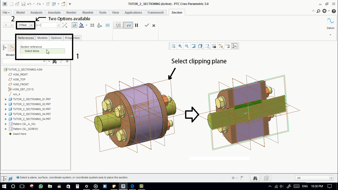
- In reference tab, we need to define the section reference. select a clipping plane for the section cut
- There are two options available, first one is through, and the second one is offset.

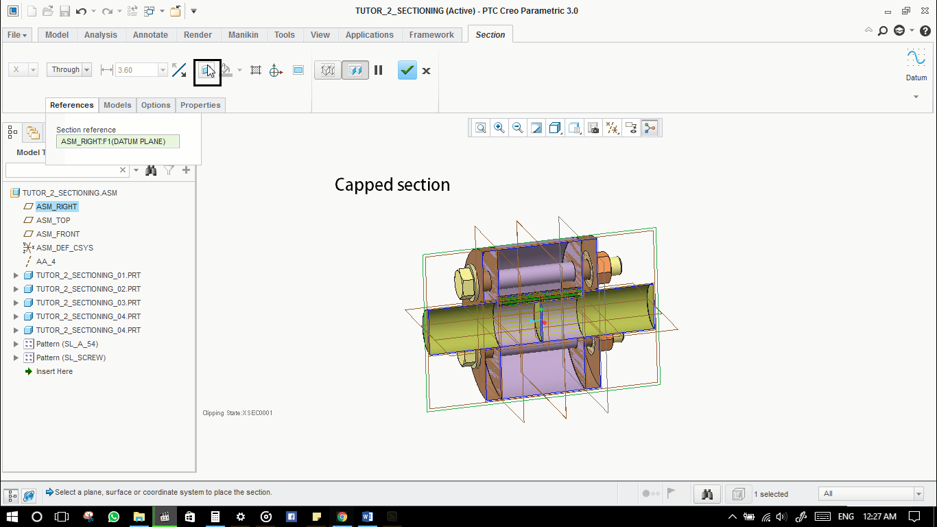
- This is capped section option. This will allow us to makes the solid body into a surface body.

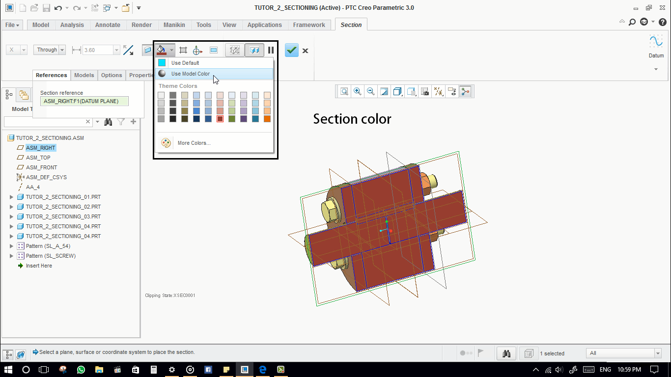
- This is the section colour. It will be applied on the sectioned surfaces.

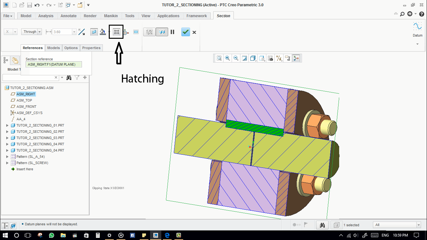
- This is hatching.

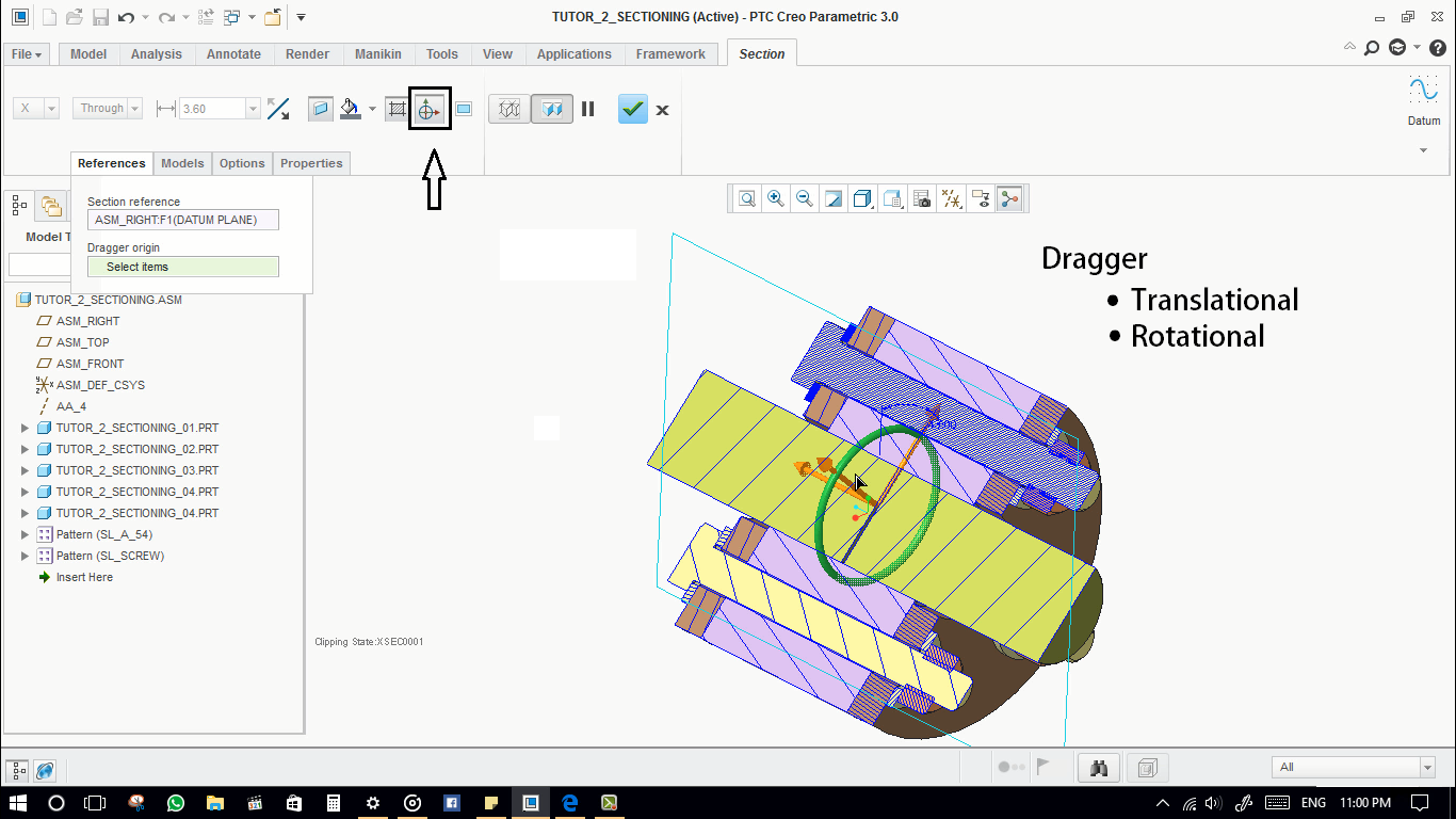
- This is dragger. Which will allow us to translate, and rotate the clipping planes orientation.

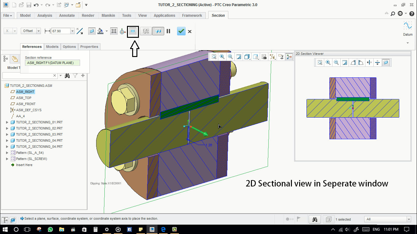
- This is a 2D view of the cross section in a separate window.

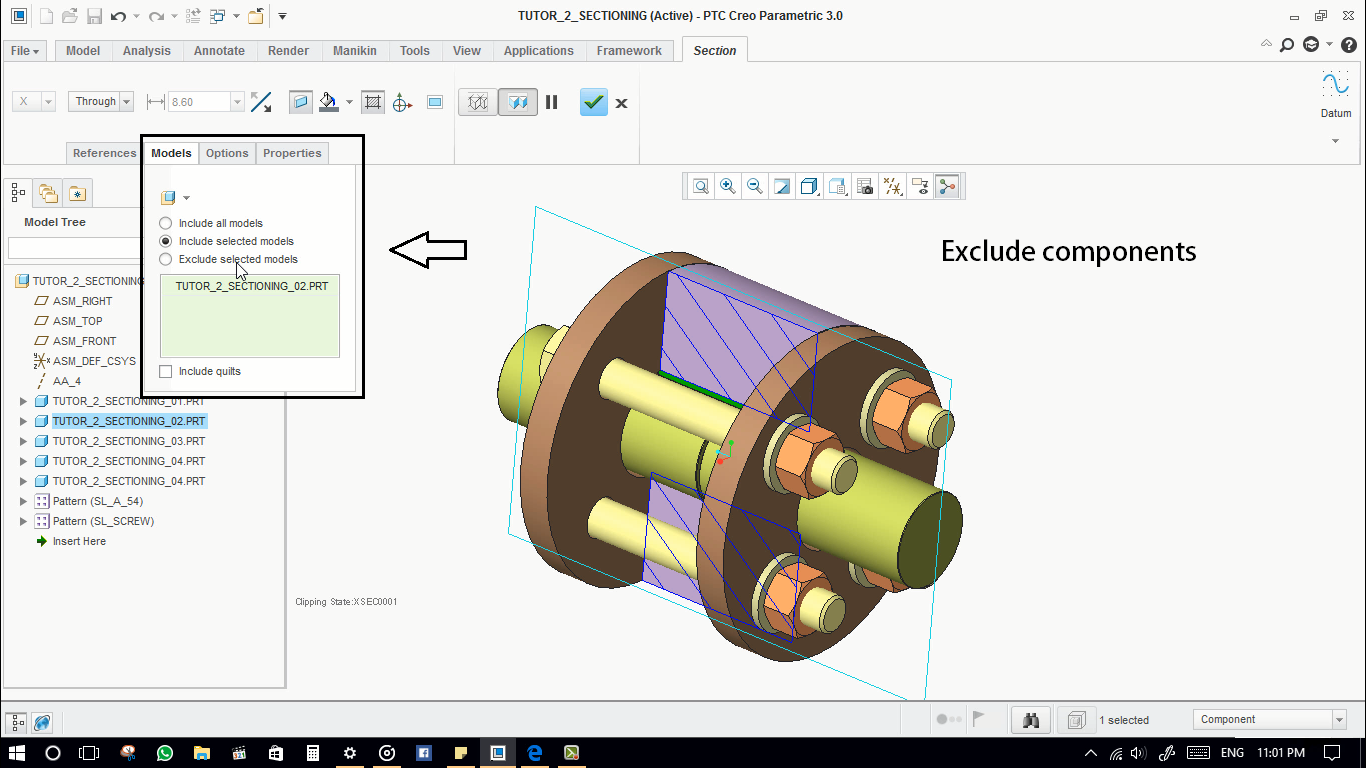
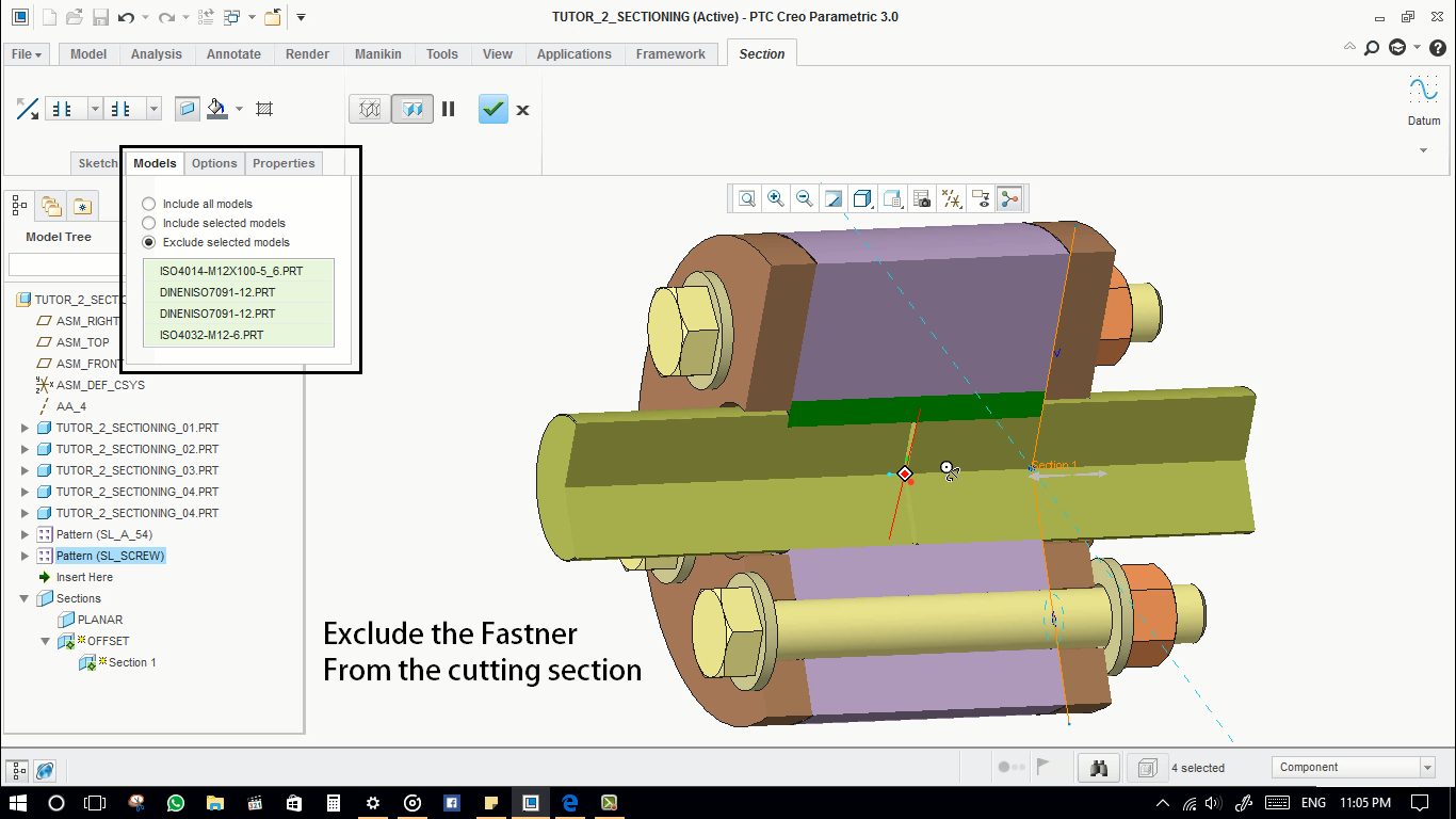
- Next, In model tab, we can actually include a particular component in a section from the assembly or exclude components in the section from the assembly. For multiple selections, use control button on your keyboard.

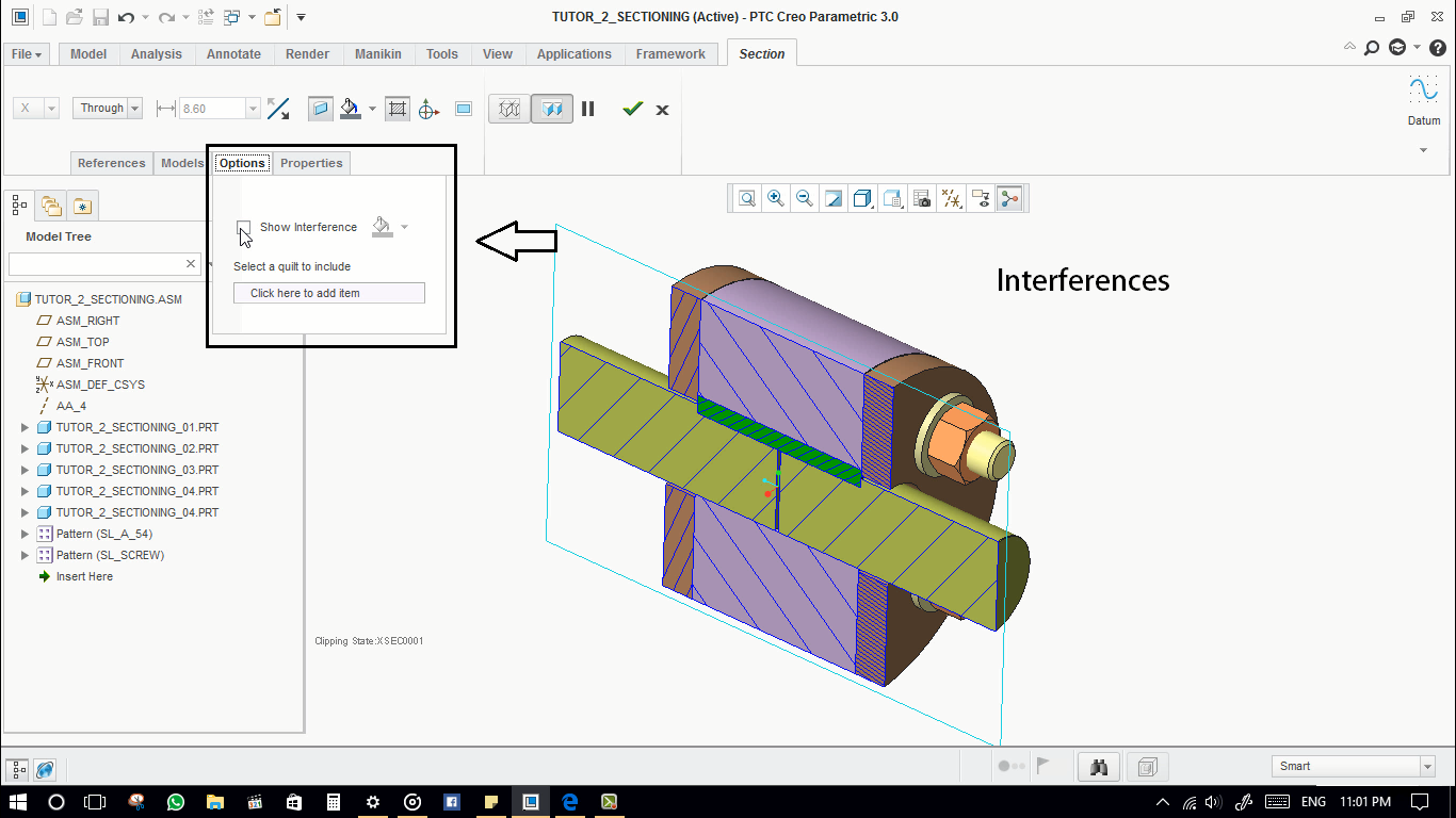
- In options tab, there is a SHOW interference feature. Which will show the interfered portions in the assembly.

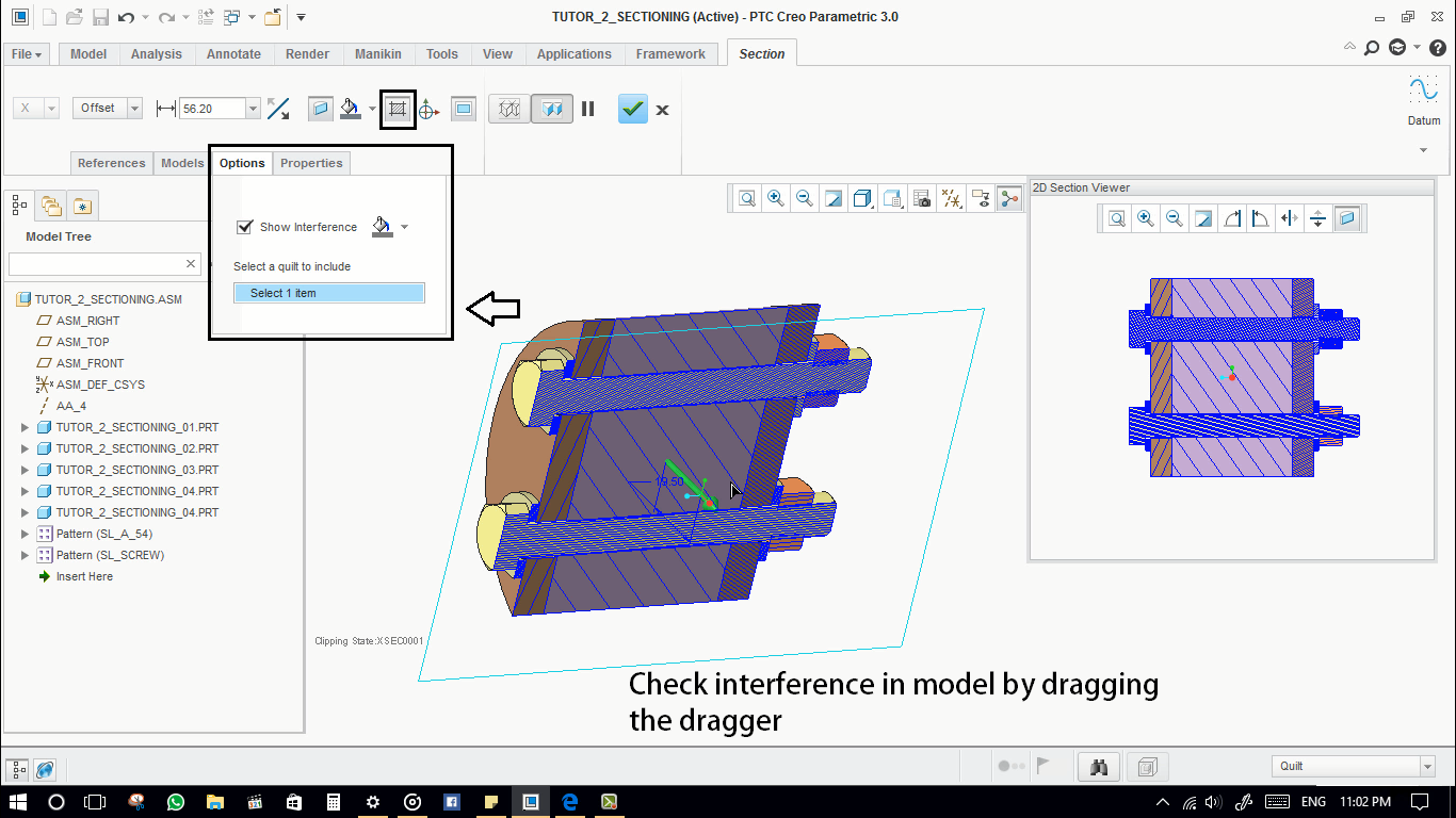
- actually, we can check the interfered portions in the entire assembly. Activate the 2D view feature. Use the dragger, to check the interfered portions. that’s it.

- These are default sections on x y z planes.

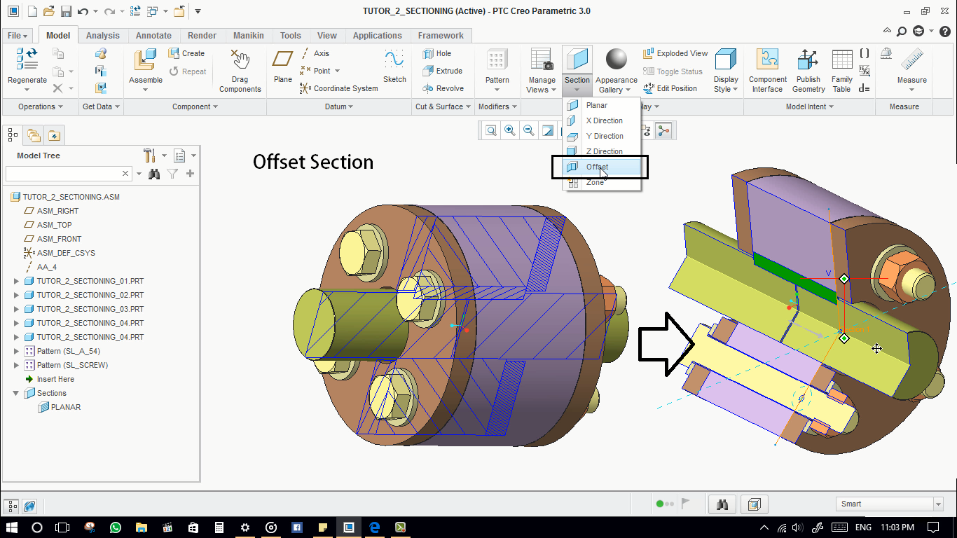
- Offset sections in Creo.

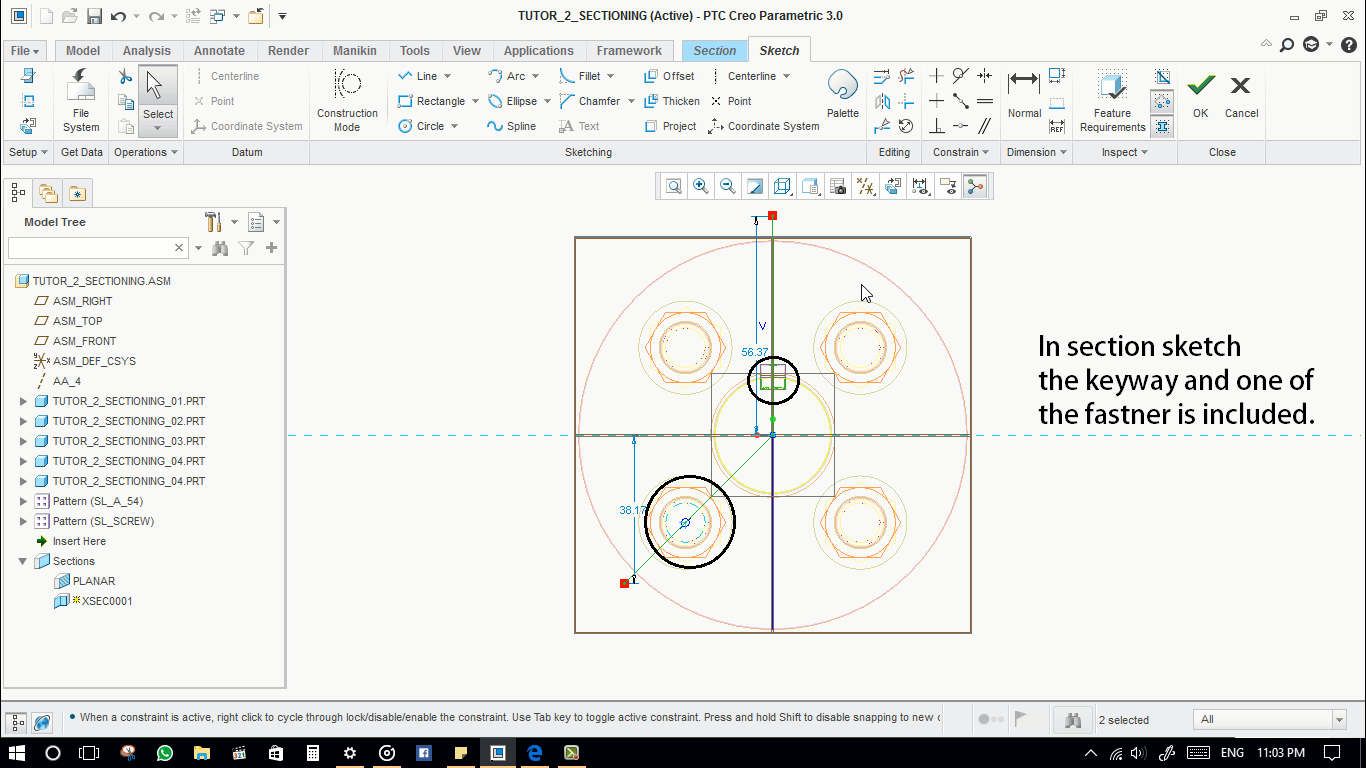
- It requires a sketch.
- Define the sketch here. We need to include the keyway and one of the fasteners in the section cut. so that draw two straight lines passing through the keyway and fastener.


-
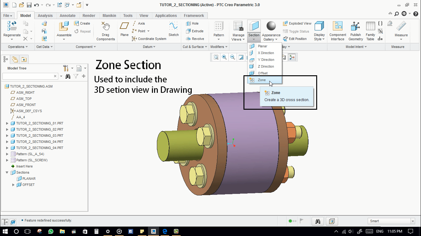
Zone section.
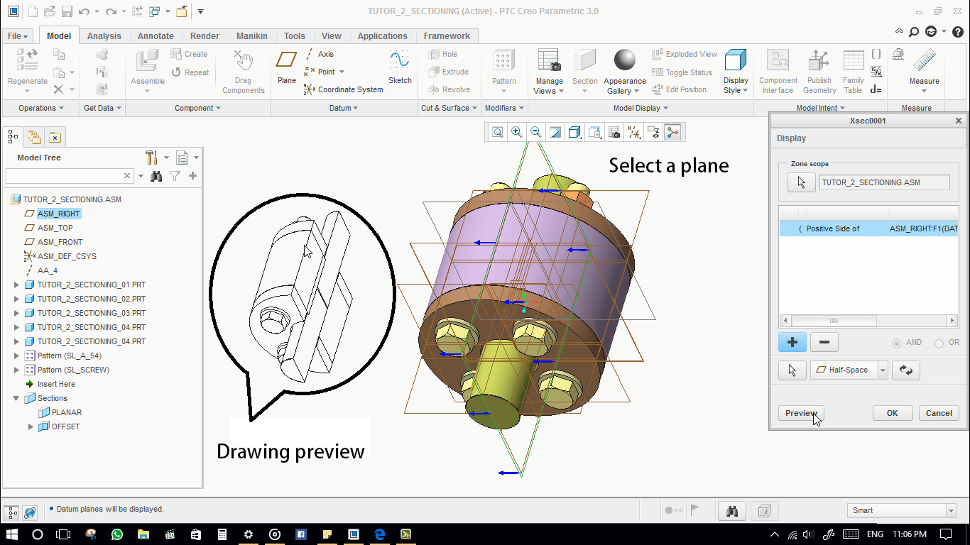
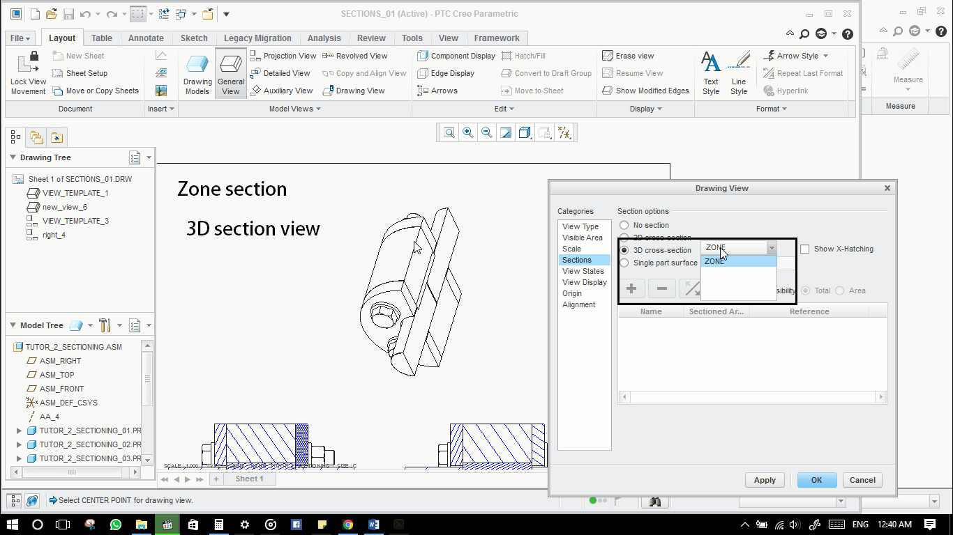
Which is used to include the 3D section view in the drawing.

- Check the direction of the arrow. To keep the material side
- Add multiple zones by adding sections. the plus sign will add new section zones.

- Create a new drawing.
- View setup for the planar view.
- View setup for the offset view.
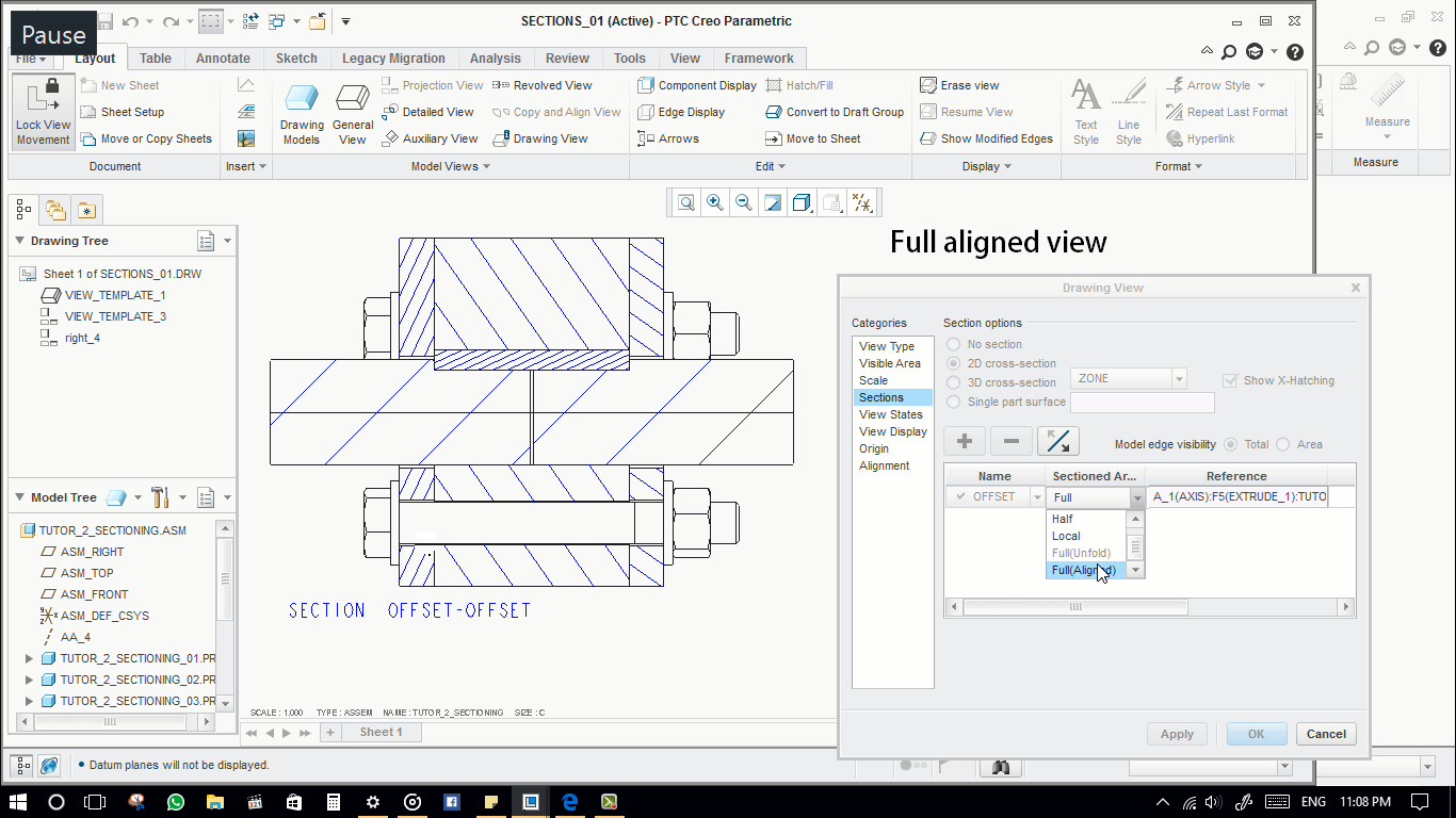
- In offset view. there is a full aligned option. and a full unfold option.
 The full aligned feature requires a centre axis. Select the centre axis for the reference.
- The full unfold option is not activated because this view is a projection. In projection view, this feature will be disabled. In general view only, this will be enabled.
-
Zone Section: 3D section view in Drawing
- Zone section is used to insert 3D section view in Drawing.Go to view properties in drawing> section> 3D sections>The Zone sections will appear, select the defined zone section.




 The full aligned feature requires a centre axis. Select the centre axis for the reference.


Leave a Reply