Hydraulic machines are those that convert either hydraulic energy (energy possessed by water) into mechanical energy (which is further converted into electrical energy ) or mechanical energy into hydraulic energy. The hydraulic machines, which convert the hydraulic energy into mechanical energy, are called turbines while the hydraulic machines which convert the mechanical energy into hydraulic energy are called pumps. Radial flow turbines are one of the types of turbines in which the water flows in the radial direction. Let us discuss more details such as Parts, construction, Working, Work done, and Efficiency of the Radial flow Turbine.
Radial Flow Reaction Turbine
Radial Flow Reaction Turbines are those turbines in which the water flows in the radial direction. The water may flow radially from outwards to inwards (i.e., towards the axis of rotation) or from inwards to outwards. If the water flows from outwards to inwards through the runner, the turbine is known as an Inward radial flow Reaction turbine. And if the water flows from inwards to outwards, the turbine is known as an Outward radial flow reaction turbine.
A reaction turbine means that the water at the inlet of the turbine possesses kinetic energy as well as pressure energy. As the water flows through the runner, a part of the pressure energy goes on changing into kinetic energy. Thus the water through the runner is under pressure. The runner is completely enclosed in an air-tight casing and casing and the runner is always full of water.
Radial Flow Reaction Turbine Main Parts
The main parts of a radial flow reaction turbine are:
- Casing
- Runner
- Guide mechanism
- Draft-tube
1. Casing
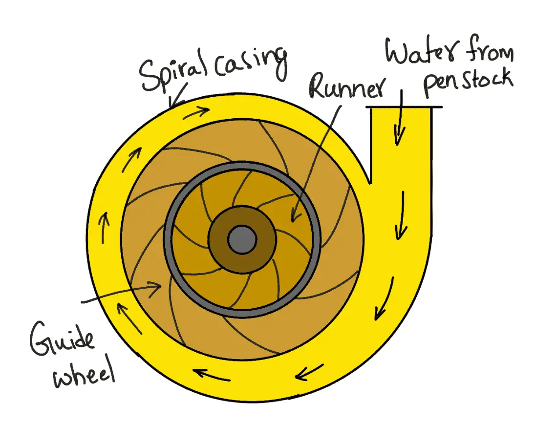
As mentioned above that in the case of a reaction turbine, the casing and runner are always full of water. The water from the penstocks enters the casing which is of spiral shape in which the area of the casing cross-section goes on decreasing gradually. The casing completely surrounds the runner of the turbine. The casing as shown in the following figure is made of a spiral shape, so the water may enter the runner at constant velocity throughout the circumference of the runner. The casing is made of concrete, cast steel or plate steel.
2. Guide Mechanism
It consists of a stationary circular wheel all around the runner of the turbine. The stationary guide vanes are fixed on the guide mechanism. The guide vanes allow the water to strike the vanes fixed on the runner without shock at the inlet. Also by a suitable arrangement, the width between two adjacent vanes of the guide mechanism can be altered so that the amount of water striking the runner can be varied.
3. Runner
It is a circular wheel on which a series of radial curved vanes are fixed. The surface of the vanes is made very smooth. The radial curved vanes are so shaped that the water enters and leaves the runner without shock. The runners are made of cast steel, cast iron or stainless steel. They are keyed to the shaft.
4. Draft-tube
The pressure at the exit of the runner of a reaction turbine is generally less than atmospheric pressure. The water at the exit cannot be directly discharged to the tail race. A tube or pipe of the gradually increasing area is used for discharging water from the exit of the turbine to the tail race. This tube of the increasing area is called a draft tube.
Inward Radial Flow Reaction Turbine
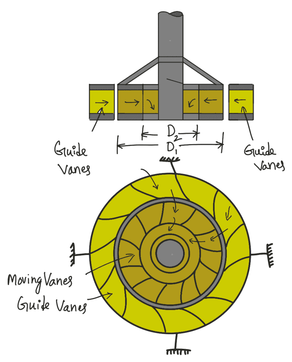
The above figure shows an inward radial flow turbine, in which case the water from the casing enters the stationary guiding wheel. The guiding wheel consists of guide vanes which direct the water to enter the runner which consists of moving vanes. The water flows over the moving vanes in the inward radial direction and is discharged at the inner diameter of the runner. The outer diameter of the runner is the inlet and the inner diameter is the outlet.
Velocity Triangles and Work done by Water on Runner
In the previous article, we discussed in detail the force exerted by the water on the radial curved vanes fixed on a wheel. From the force exerted on the vanes, the work done by water, the horsepower given by the water to the vanes and the efficiency of the vanes can be obtained.
Also, we have drawn velocity triangles at the inlet and outlet of the moving radial vanes in that article. From the velocity triangles, the work done by the water on the runners, horsepower and efficiency of the turbine can be obtained.
The work done per second on the runner by water is given by equation from the previous article as follows
W = ρaV1 (Vw1 u1 ± Vw2 u2)
W = ρQ (Vw1 u1 ± Vw2 u2)
…. Equation (a)
Equation (a) also represents the energy transfer per second to the runner.
Where
Vw1 = Velocity of whirl at the inlet,
Vw2 = Velocity of whirl at the outlet
u1 = Tangential velocity of the wheel at the inlet = (π D1 × N) ÷ 60
u2 = Tangential velocity of the wheel at the outlet = (π D2 × N) ÷ 60
D1 = Outer diameter of runner
D2 = Inner diameter of runner
The work done per second per unit weight of water per second.
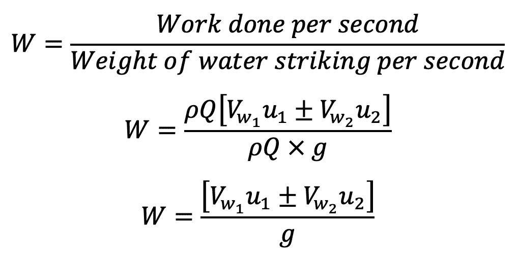
Equation (b) represents the energy transfer per unit weight/s to the runner. This equation is known as Euler’s equation of hydrodynamics machines. This is also known as the fundamental equation of hydrodynamic machines. This equation was given by Swiss scientist L. Euler.
In equation (b), the + ve sign is taken if angle ß is an acute angle. If ß is an obtuse angle then the – ve sign is taken.
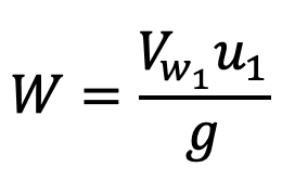
If ß = 90°, then Vw2= 0 and work done per second per unit weight of water striking/s become as
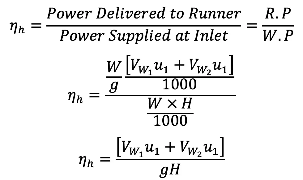
Hydraulic efficiency is obtained from the hydraulic turbines article discussed previously as follows.
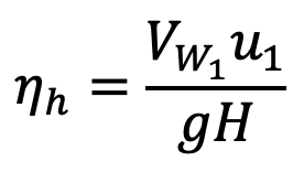
If the discharge is radial at the outlet, then Vw2 = 0
Degree of Reaction
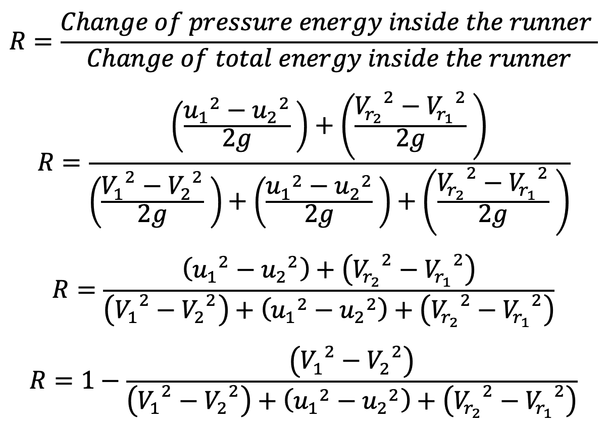
The degree of reaction is defined as the ratio of pressure energy change inside a runner to the total energy change inside the runner. It is represented by ‘R’. Hence mathematically it can be written as
Francis Turbine
The inward flow reaction turbine having radial discharge at the outlet is known as Francis Turbine, after the name of J.B. Francis, an American engineer who at the beginning designed the inward radial flow reaction type of turbine. In the modern Francis turbine, the water enters the runner of the turbine in the radial direction at the outlet and leaves in the axial direction at the inlet of the runner. Thus the modern Francis Turbine is a mixed-flow type turbine.
The velocity triangle at the inlet and outlet of the Francis turbine is drawn in the same way as in the case of an inward flow reaction turbine. As in the case of the Francis turbine, the discharge is radial at the outlet, and the velocity of the whirl at the outlet (i.e., Vm) will be zero. Hence the work done by water on the runner per second will be
W = ρQ (Vw1 u1)
And work done per second per unit weight of waterstriking/s = 1/g [Vw1 u1]
The Hydraulic efficiency of Francis Turbine will be

Design Parameters of Francis Turbine
- The ratio of the width of the wheel to its diameter is given as n = B1 / D1 The value of varies from 0.10 to 0.40.
- The flow ratio is given as follows and varies from 0.15 to 0.30.

- The speed ratio is given as follows and Varies from 0.6 to 0.9.

Outward Radial Flow Reaction Turbine
The following Figure shows the outward radial flow reaction turbine in which the water from the casing enters the stationary guide wheel. The guide wheel consists of guide vanes that direct water to enter the runner which is around the stationary guide wheel. The water flows through the vanes of the runner in the outward radial direction and is discharged at the outer diameter of the runner. The inner diameter of the runner is the inlet and the outer diameter is the outlet.
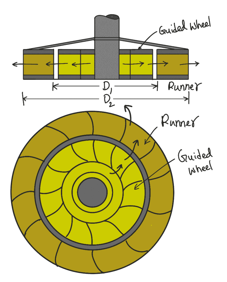
The velocity triangles at the inlet and outlet will be drawn by the same procedure as adopted for the inward flow turbine. The work done by the water on the runner per second, the horsepower developed and hydraulic efficiency will be obtained from the velocity triangles. In this case, as an inlet of the runner, I sat the inner diameter of the runner, the tangential velocity at the inlet will be less than that of an outlet, i.e.
u1 < u2 , as D1 < D2
This is all about the Radial Flow Reaction Turbines. Let us know what you think about this article in the comment section below.

Leave a Reply