Hydraulic machines are those that convert either hydraulic energy (energy possessed by water) into mechanical energy (which is further converted into electrical energy ) or mechanical energy into hydraulic energy. The hydraulic machines, which convert the hydraulic energy into mechanical energy, are called turbines while the hydraulic machines which convert the mechanical energy into hydraulic energy are called pumps. According to the type of energy available at the inlet The Pelton wheel or Pelton turbine is a tangential flow impulse turbine. Let us discuss more details such as Parts, construction, Working, Work done, and Efficiency of the Pelton Turbine.
Pelton Turbine
The Pelton wheel or Pelton turbine is a tangential flow impulse turbine. The water strikes the bucket along the tangent of the runner. The energy available at the inlet of the turbine is only kinetic energy. The pressure at the inlet and outlet of the turbine is atmospheric. This turbine is used for high heads and is named after L.A. Pelton, an American Engineer. The following Figure shows the layout of a hydroelectric power plant in which the turbine is a Pelton wheel.
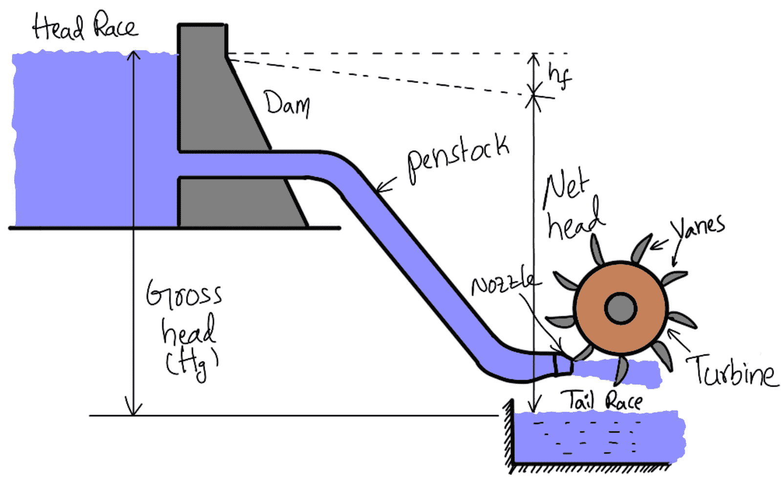
The water from the reservoir flows through the penstocks at the outlet to which a nozzle is fitted. The nozzle increases the kinetic energy of the water flowing through the penstock. At the outlet of the nozzle, the water comes out in the form of a jet and strikes the buckets (vanes) of the runner.
The main parts of the Pelton turbine are
- Nozzle and flow regulating arrangement (spear)
- Runner and buckets
- Casing
- Breaking jet
Nozzle and Flow Regulating Arrangement:
The amount of water striking the buckets (vanes) of the runner is controlled by providing a spear in the nozzle as shown in the following figure.
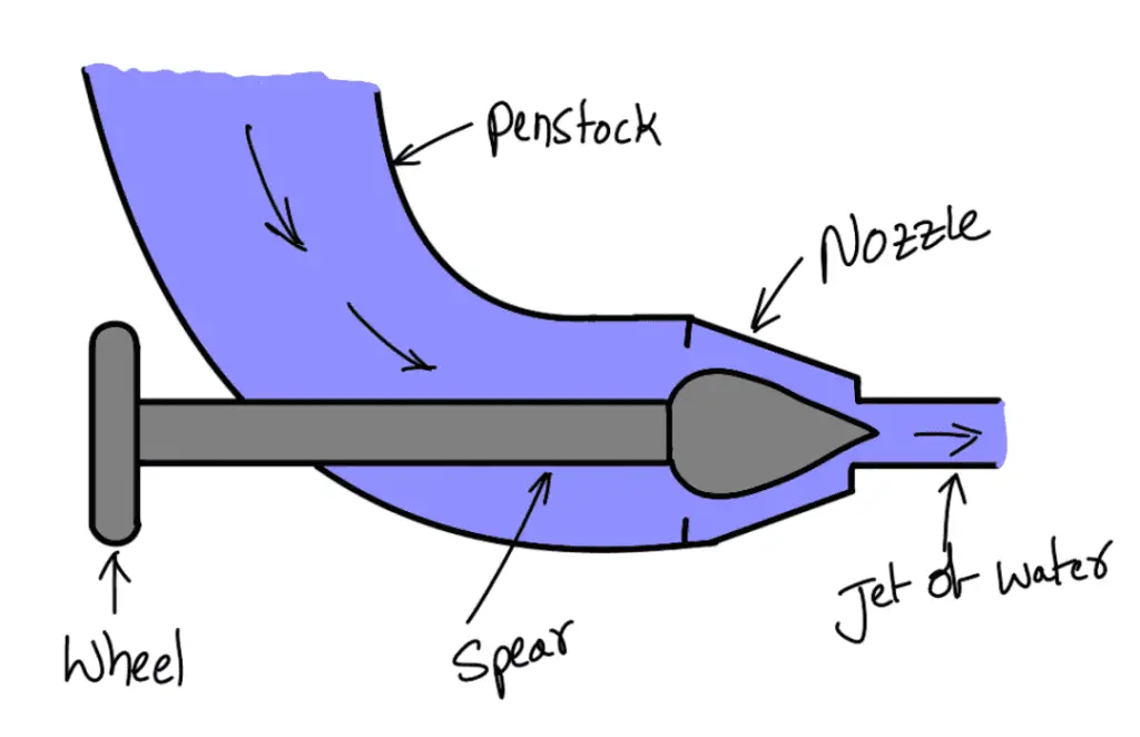
The spear is a conical needle which is operated either by a hand wheel or automatically in an axial direction depending upon the size of the unit. When the spear is pushed forward into the nozzle the amount of water striking the runner is reduced. On the other hand, if the spear is pushed back, the amount of water striking the runner increases.
Runner with Buckets
The following figure shows the runner of a Pelton wheel. It consists of a circular disc on the periphery of which a number of buckets evenly spaced are fixed. The shape of the buckets is a double hemispherical cup or bowl. Each bucket is divided into two symmetrical parts by a dividing wall which is known as the splitter.
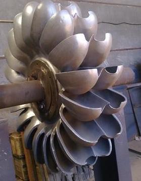
The jet of water strikes the splitter. The splitter divides the jet into two equal parts and the jet comes out at the outer edge of the bucket. The buckets are shaped in such a way that the jet gets deflected through 160° or 170°. The buckets are made of cast iron, cast steel bronze or stainless steel depending upon the head at the inlet of the turbine.
Casing
The Following figure shows a Pelton turbine with a casing. The function of the casing is to prevent the splashing of the water and to discharge water to the tail race.
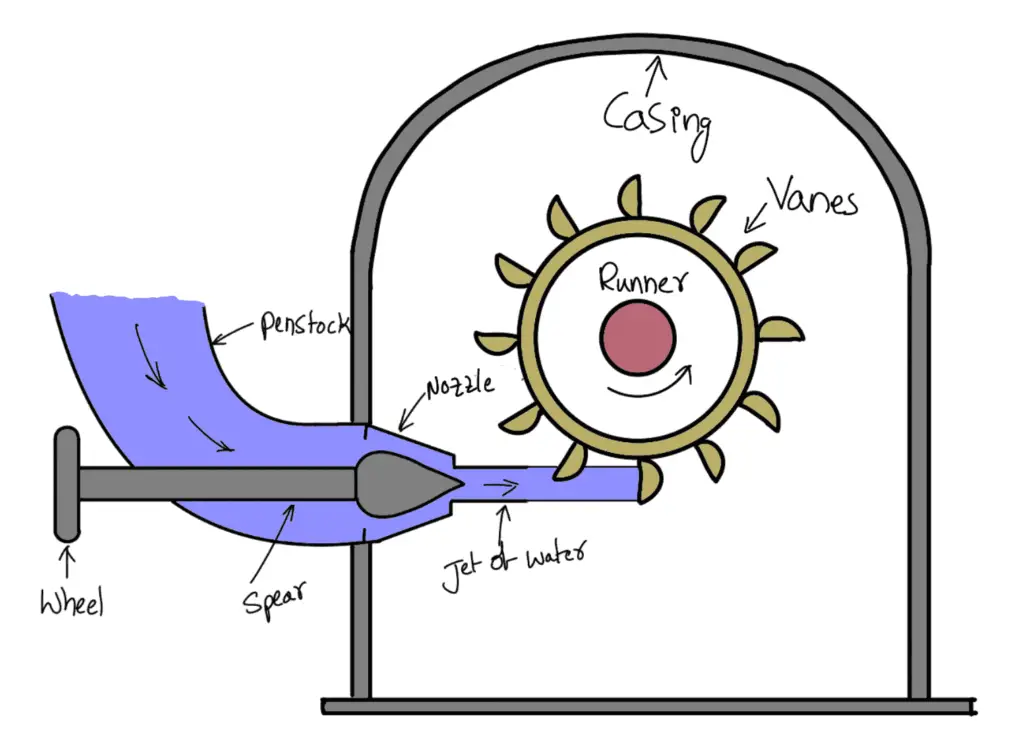
It also acts as a safeguard against accidents. It is made of cast iron or fabricated steel plates. The casing of the Pelton wheel does not perform any hydraulic function.
Breaking Jet
When the nozzle is completely closed by moving the spear in the forward direction, the amount of water striking the runner reduces to zero. But the runner due to inertia goes on revolving for a long time. To stop the runner in a short time, a small nozzle is provided which directs the jet of water to the back of the vanes. This jet of water is called a breaking jet.
Velocity Triangles for Pelton Turbine
The following figure shows the shape of the vanes or buckets of the Pelton wheel. The jet of water from the nozzle strikes the bucket at the splitter, which splits up the jet into two parts. These parts of the jet, glide over the inner surfaces and come out at the outer edge.
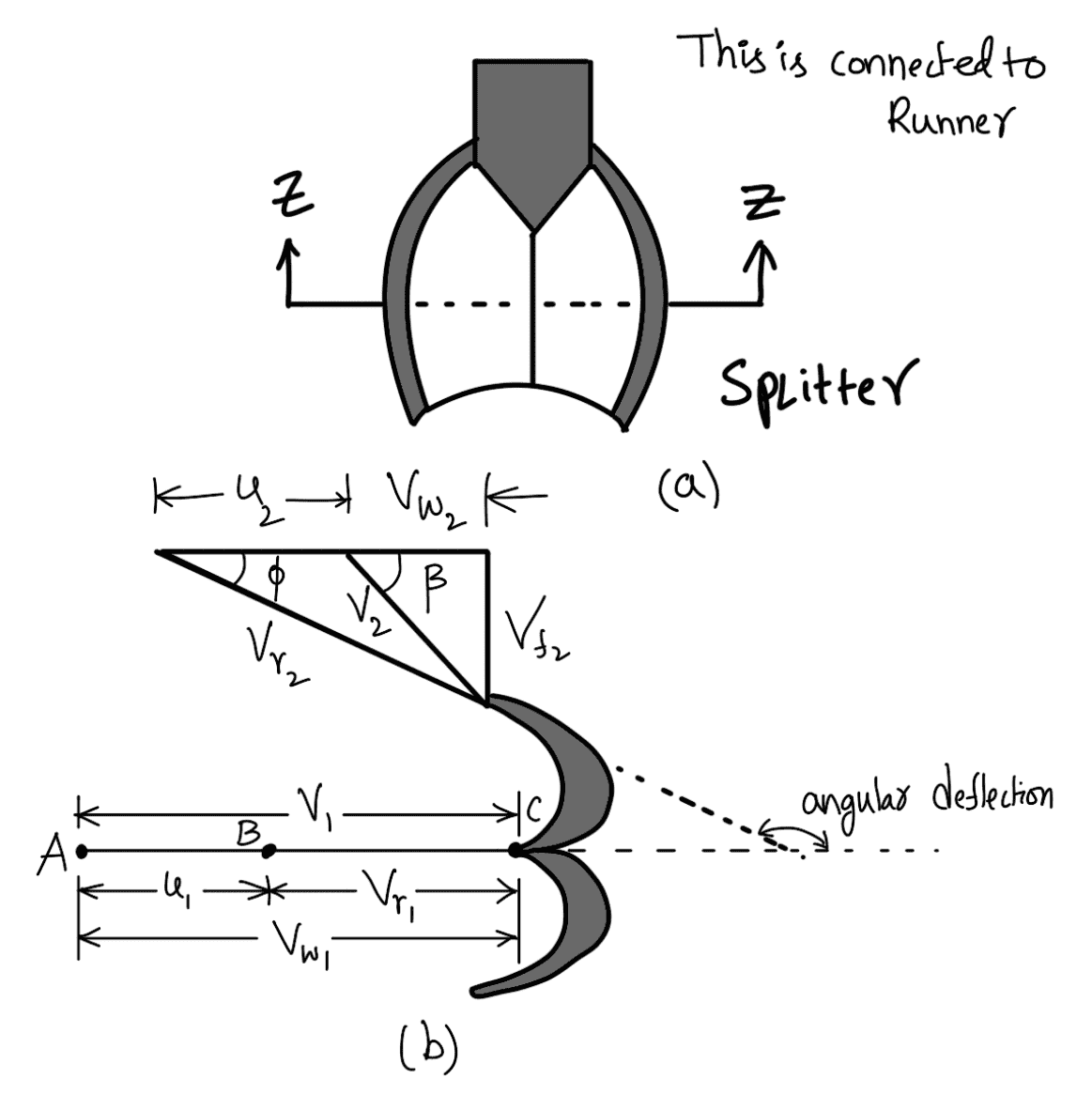
Figure (b) shows the section of the bucket at Z-Z. The splitter is the inlet tip and the outer edge of the bucket is the outlet tip of the bucket. The inlet velocity triangle is drawn at the splitter and the outlet velocity triangle is drawn at the outer edge of the bucket, by the same method as explained in the Previous article.
Let H = Net head acting on the Pelton wheel
H = Hg – hf
where
Hg = Gross head
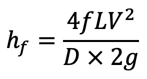
V = Velocity of flow in the penstock
L = Length of the penstock
D = Diameter of the penstock
Then
V1 = Velocity of the jet at inlet = √(2gH)

The velocity triangle at the inlet will be a straight line where
Vr1 = V1 – u1
Vr1 = V1– u
Vw1 = V1
α = 0° and θ = 0°
From the velocity triangle at the outlet, we have
Vr2 = Vr1
Vw2 = Vr2 cos φ – u2
The force exerted by the jet of water in the direction of motion is given by equation as we discussed in the previous article as
Fx = ρaV1 (Vw1 + Vw2)
…. Equation (a)
As the angle ß is an acute angle, + ve sign should be taken.
Also, this is the case of a series of vanes, the mass of water striking is ρaV1, and not ρaVr1. In equation (a), ‘a’ is the area of the jet which is given as
a = Area of jet = (π/4)d2
Work done for Pelton Wheel
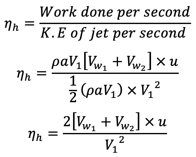
Now work done by the jet on the runner per second
W = Fx × u
W = ρaV1, [Vw1 + Vw2] × u Nm/s
The power is given to the runner by the jet

Work done/s per unit weight of water striking/s
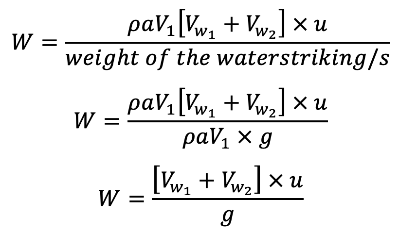
The energy supplied to the jet at the inlet is in the form of kinetic energy and is equal to ½ mV2
The Kinetic Energy of the jet per second = ½ ρaV1 × V12
Hydraulic efficiency
Now
Vw1 = V1
Vr1 = V1 – u1 = (V1 – u)
Vr2 = (V1 – u)
Vw2 = Vr2 cos φ – u2 = Vr2 cos φ – u2 = (V1 – u) cos φ – u2
Substituting the values of Vw1 and Vw2 in equation (d),
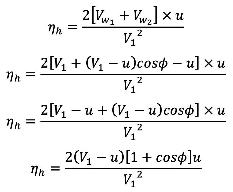
This is the equation for the efficiency of Pelton Turbine.
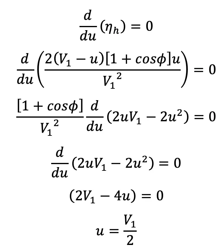
The efficiency will be maximum for a given value of V1 when
Maximum Efficiency Condition
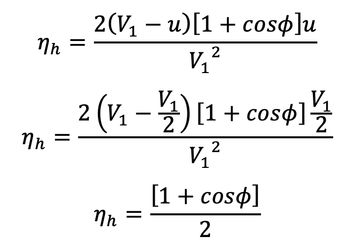
Equation (f) states that the hydraulic efficiency of a Pelton wheel will be maximum when the velocity of the wheel is half the velocity of the jet of water at the inlet. The expression for maximum efficiency will be obtained by substituting the value of u = Y in equation (e).
The maximum Efficiency Condition for Pelton Wheel or Pelton Turbine is
Points to be Remembered for Pelton Wheel
- The velocity of the jet at the inlet is given by V1 = Cv √ (2gH)
where Cv = Coefficient of velocity = 0.98 or 0.99
H = Net head on turbine - The velocity of the wheel (u) is given by u = φ √ (2gH)
where φ = Speed ratio. The value of the speed ratio varies from 0.43 to 0.48. - The angle of deflection of the jet through buckets is taken at 165° if no angle of deflection is given.
- The mean diameter or the pitch diameter D of the Pelton wheel is given by u

- Jet Ratio is defined as the ratio of the pitch diameter (D) of the Pelton wheel to the diameter of the jet (d). It is denoted by ‘m’ and is given as

- Number of buckets on a runner is given by

- Number of Jets. It is obtained by dividing the total rate of flow through the turbine by the rate of flow of water through a single jet.
Design of Pelton Wheel
The design of the Pelton wheel means the following data is to be determined
- Diameter of the jet (d),
- Diameter of the wheel (D),
- Width of the buckets which is = 5 × d,
- Depth of the buckets which is = 1.2 × d
- Number of buckets on the wheel.
Size of buckets means the width and depth of the buckets.
Let us solve an Example Problem Design the Pelton Turbine
Example Problems to Design Pelton Turbine
Problem Statement: A Pelton wheel is to be designed for the following specifications:
Shaft power = 11,772 kW, Head = 380 metres, Speed = 750 r.p.m, Overall efficiency = 86% and the Jet diameter is not to exceed one-sixth of the wheel diameter. Determine the following :
(i) The wheel diameter
(i) The number of jets required
(iii) Diameter of the jet
Answer:
Shaft power S.P. = 11,772 kW
Head H = 380 metres
Speed N = 750 r.p.m
Overall efficiency η0 = 86%
The ratio of jet diameter to wheel diameter
Co-efficient of velocity Kv1 = Cv = 0.985
Speed ratio, Ku1 = 0.45
Velocity of jet, V1 = Cv √ (2gH) = 0.985 √ (2 × 9.81 × 380) = 85.05 m/s
The velocity of wheel, u = u1 = u2
u = Speed ratio × √(2gH) = 0.45 × √(2 × 9.81 × 380) = 38.85 m/s
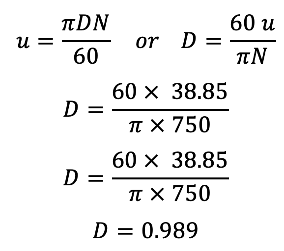
The Pelton wheel Diamter D is 0.0989 meters.
But we have the diameter ratio as follows
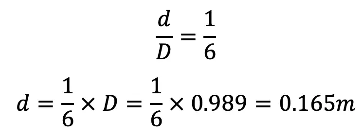
Discharge of one jet, q = Area of jet × Velocity of jet

From the given overall Efficiency
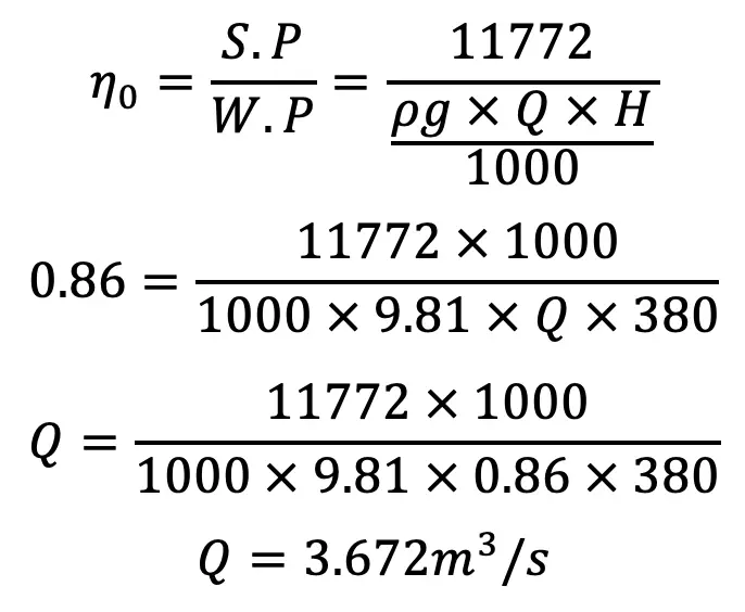
The total Discharge is 3.672 m3/s
The Number of jets

This is all about the Pelton Turbine Parts, construction, Working, Work done, and Efficiency. Let us know what you think about this article in the comment section below.

Leave a Reply