An Orifice Meter is a device used for measuring the rate of now of a fluid through a pipe. It also works on the same Bernoulli’s principle as that of the Venturimeter. It is a cheaper device compared to Venturimeter. Let us discuss more details of the Orifice Meter such as the construction, working principle, different parts, and more…

Orifice Meter
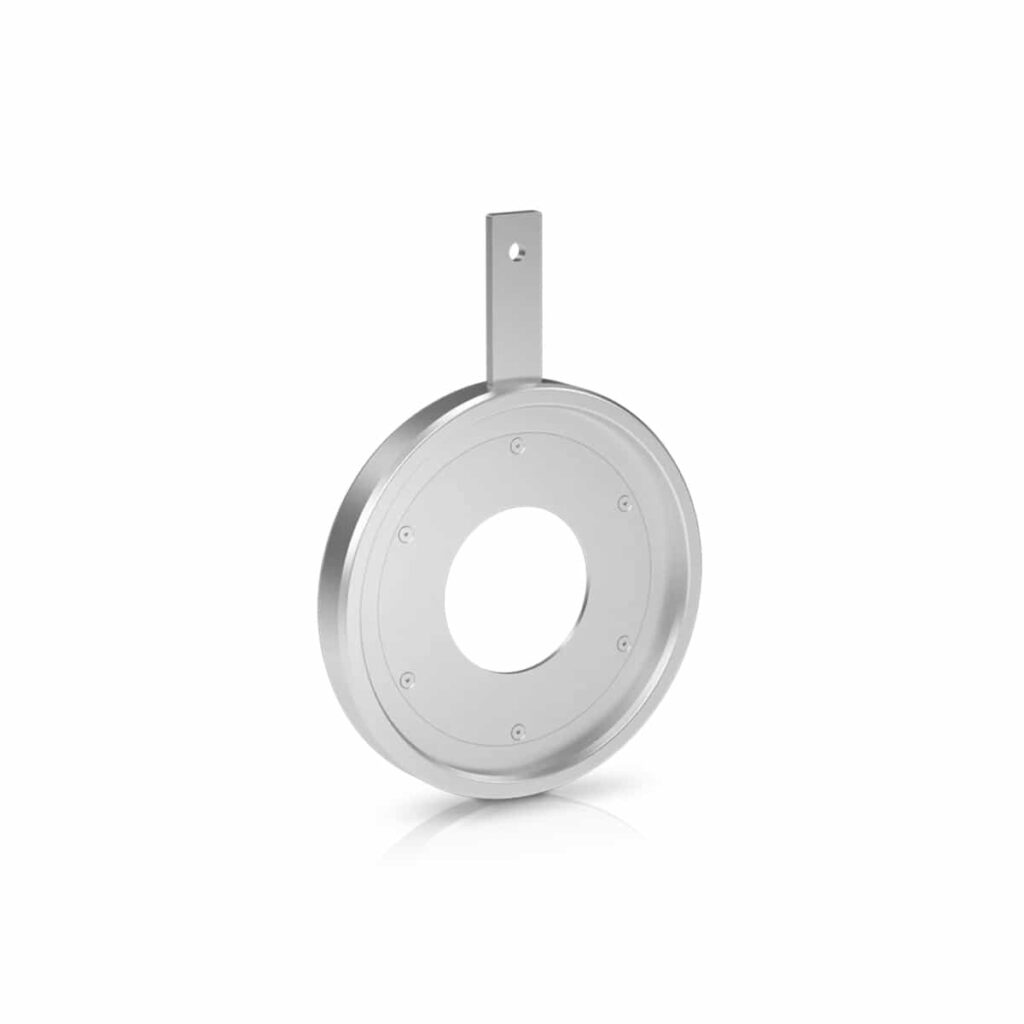
It consists of a flat circular plate with a circular sharp-edged hole called an orifice, which is concentric with the pipe. The orifice diameter is generally kept 0.5 times the diameter of the pipe, though it may vary from 0.4 to 0.8 times the pipe diameter.
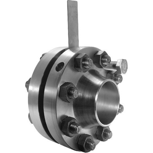
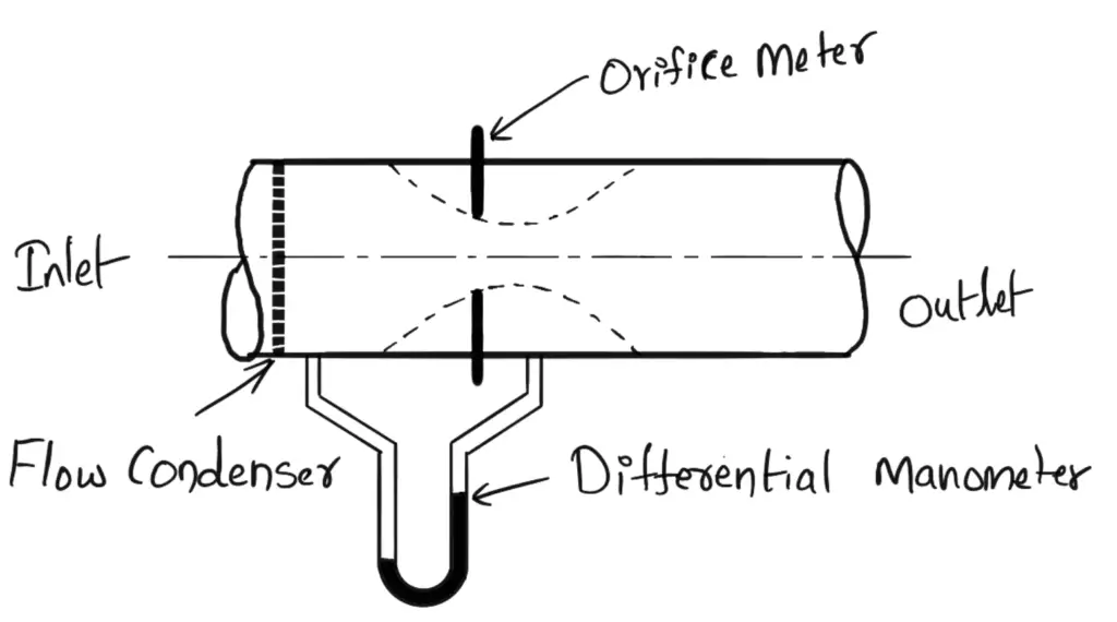
Orifice Meter Parts and Construction
- Inlet Section
- Orifice Plate
- Flow Conditioner
- Outlet Section
- Differential Manometer
1. Inlet Section
The Inlet section is the linear segment extending from the device and acts as a front-end connection for the fluid flowing inside.
2. Orifice Plate
The orifice plate is situated between the inlet and outlet and the plate is used to generate a pressure drop that will enable the flow rate which enables the measurement of the flow rate.
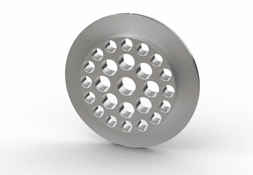
3. Flow Conditioner
Usually, the Flow Conditioner is installed in the inlet section of the meter tube and is used to enhance linear flow in the inlet section of the meter tube.
4. Outlet Section
The Outlet Section is the linear segment similar to the inlet section where the pressure of the gas or fluid discharged is determined.
5. Differential Manometer
The differential manometer is a device used for measuring the difference in pressures between two points in a pipe or in two different pipes. A differential manometer consists of a U-tube, containing a heavy liquid, whose two ends are connected to the two points, whose difference in pressure is to be measured.
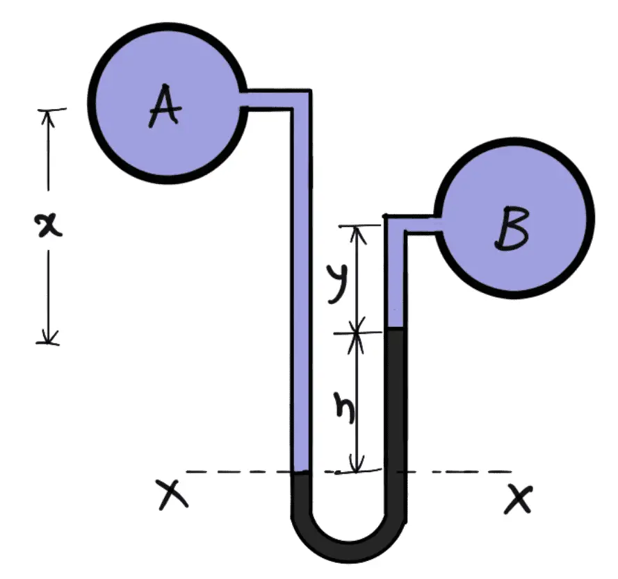
Read more details about the Differential manometers…
Orifice Meter Working Principle
- Orifice Meter Works is based on the principle of Bernoulli’s equation.
- In Orifice Meter, there is a pipe in which fluid is passing from one side to another side that is an inlet section to the outlet section.
- A differential manometer is attached between the two points to measure the pressure differences between these two points.
- A flow condenser also can be installed on the inlet section of the Orifice meter to enhance the linear flow of the fluid. (Flow Condenser is a filter-type section which guides the fluid flow in very linear motion).
- Now we place an orifice plate which is thin in size and has a small hole in between through which the fluid will pass.
- Due to the very small concentric hole of the orifice, the velocity increases, the decrease in pressure and vice versa.
- The place of the orifice plate in the pipe only determines the flow rate or discharge at that point only.
- The discharge through the orifice plate can be calculated by the formula specified in the below section.
Expression for Rate of flow through Orifice Meter
A differential manometer is connected at section (1), which is at a distance of about 1.5 to 2.0 times the pipe diameter upstream from the orifice plate, and at section (2), which is at a distance of about half the diameter of the orifice on the downstream Side from the orifice plate.
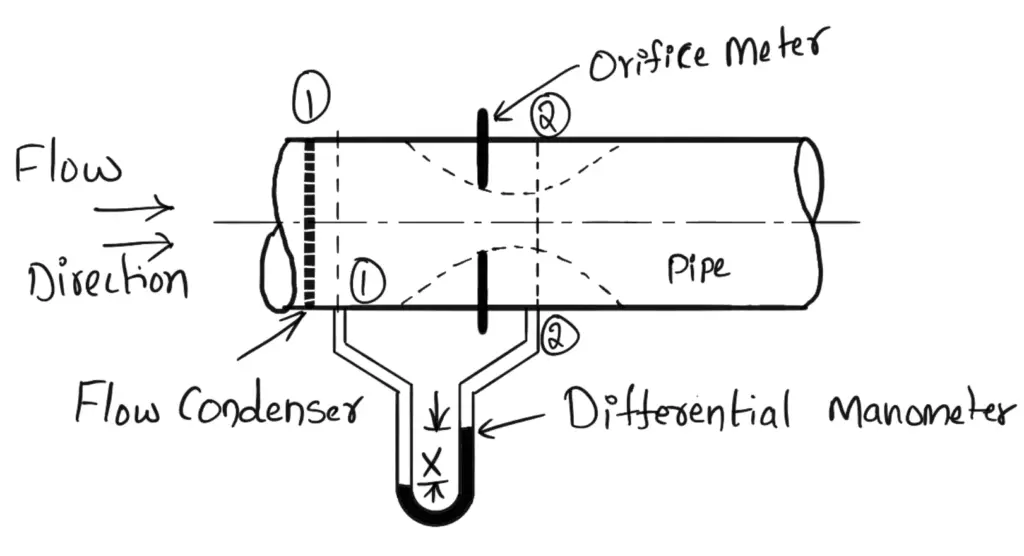
Let
p1 =Prevsure at section (1)
v1 = velocity at section (1)
a1 = area Of pipe at section (1)
p1, v1, and a1 are the corresponding values in section (2)
Let us apply Bernoulli’s Equation at sections (1) and (2) we get,
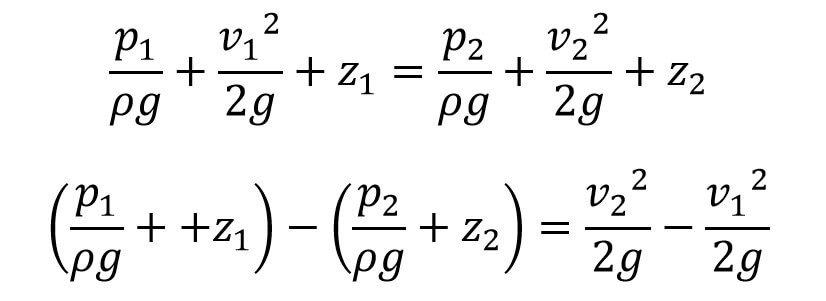
But we have the differential Head h

Substituting this h value in the above equation we get,
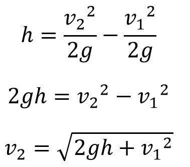
Now section (2) is at the venta-contracta and a2 represents the area at the venta-contracta.
if a0 is the area of office then we have
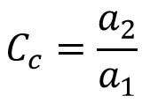
Where Cc =Coefficient of contraction
a2 = a0 × Cc
By Continuity equation, we have
a1 v1 = a2 v2
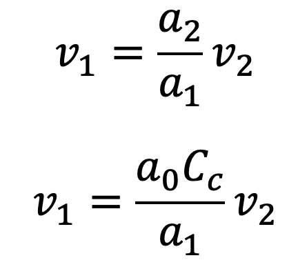
Substitute the value of v1 in Equation (a), and we get
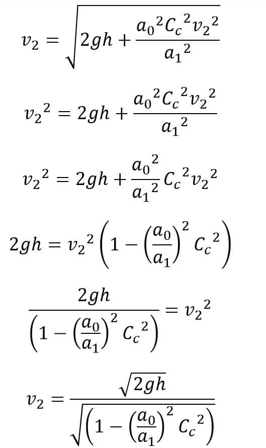
We know the discharge of any fluid flow
Q = v2 × a2
Q = v2 × a0 × Cc
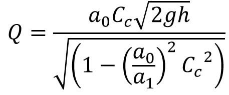
The above expression can be simplified by using
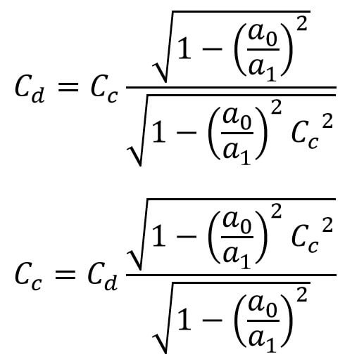
Substituting this value of Cc in equation (b), we get
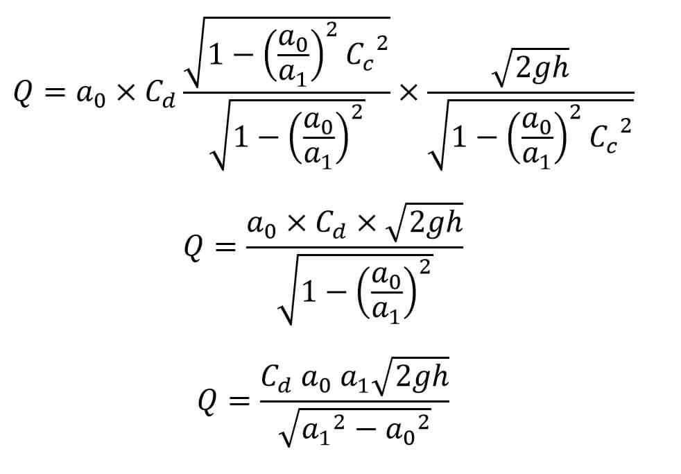
This is the expression for the flow discharge through the orifice. where Cd is the Coefficient of discharge for the orifice meter.
OrificeMeter Applications
An Orifice Meter can measure the flow rate of fluids in their single state as either a gaseous state or liquid state and also be used to measure the flow rate of fluids in a mixed state that is both gaseous and liquid states, such as wet steam, or natural gas with water.
The orifice meter’s main application is used at several places to measure flow rates such as
- Water Treatment Plants,
- Natural Gas
- Petrochemicals
- Oil Filtration Plants
- Refineries.
OrificeMeter Advantages
- The Orifice meter is very cheap compared to other flow meters like the venturi meter.
- The orifice meter alignment can be vertical, horizontal, and inclined as required.
- The space required for the Orifice meter installation is less.
- As you can see from the orifice plate image above, this plate is thin enough to fit between an existing pipe.
- The maintenance cost for the orifice meter is low.
- It offers very less pressure drop.
- The construction and design of this orifice meter are very simple.
- It is capable to determine a wide range of flow rates the main advantage.
OrificeMeter Disadvantages
- Due to limitations in the vena-contracta length, the minimum pressure for reading the flow is sometimes difficult.
- In the Venturi meter, downstream pressure can be recovered. But with the Orifice meter downstream pressure can not be recovered.
- The orifice Accuracy can be affected by the viscosity, density, and pressure of the fluid.
- It requires a straight pipe for good precision and accuracy.
- The 40% to 90% overall head loss of the differential pressure.
- The obtained coefficient of discharge is low.
This is all about the Orifice Meter, Let us know what you think about this article in the comment section below.

Leave a Reply