A spring is defined as an elastic body, whose function is to distort when loaded and to recover its original shape when the load is removed. It absorbs or controls energy due to either shock or vibration so it can be used as shock absorbers and vibration dampers. It is also used to apply forces, as in brakes, clutches, and spring-loaded valves. We have already discussed different types of Springs in the previous article. Let us discuss the Material for Helical Springs.

Applications of Springs
The various important applications of springs are as follows:
- To cushion, absorb, or control energy due to either shock or vibration as in car springs, railway buffers, aircraft landing gears, shock absorbers, and vibration dampers.
- To apply forces, as in brakes, clutches, and spring-loaded valves.
- To control motion by maintaining contact between two elements as in cams and followers.
- To measure forces, as in spring balances and engine indicators.
- To store energy, as in watches, toys, etc.
Types of Springs
Though there are many types of springs, the following, according to their shape, are important from the subject point of view.
- Helical springs
- Conical and volute springs
- Torsion springs
- Laminated or leaf springs
- Disc or Belleville springs
- Special-purpose springs
We have discussed more details in a separate article here!
Material for Helical Springs
The material of the spring should have high fatigue strength, high ductility, and high resilience and it should be creep-resistant. It largely depends upon the service for which they are used i.e. severe service, average service, or light service.
Severe service means rapid continuous loading where the ratio of minimum to maximum load (or stress) is one-half or less, as in automotive valve springs.
Average service includes the same stress range as in severe service but with only intermittent operation, as in engine governor springs and automobile suspension springs.
Light service includes springs subjected to loads that are static or very infrequently varied, as in safety valve springs.
The springs are mostly made from oil-tempered carbon steel wires containing 0.60 to 0.70 percent carbon and 0.60 to 1.0 percent manganese. Music wire is used for small springs. Non-ferrous materials like phosphor bronze, beryllium copper, monel metal, brass, etc., may be used in special cases to increase fatigue resistance, temperature resistance, and corrosion resistance.
The following table shows the values of allowable shear stress, modulus of rigidity, and modulus of elasticity for various materials used for springs.
The helical springs are either cold-formed or hot-formed depending upon the size of the wire. Wires of small sizes (less than 10 mm diameter) are usually wound cold whereas larger size wires are wound hot. The strength of the wires varies with size, smaller size wires have greater strength and less ductility, due to the greater degree of cold working.
Table: Values of allowable shear stress, Modulus of elasticity, and Modulus of rigidity for various spring materials.
| Material | Allowable shear stress (τ) MPa | Modulus of rigidity (G) kN/m2 | Modulus of elasticity (E)kN/mm2 | ||
| Severe service | Average service | Light service | |||
| 1. Carbon steel (a) Upto to 2.125 mm dia. (b) 2.125 to 4.625 mm (c) 4.625 to 8.00 mm (d) 8.00 to 13.25 mm (e) 13.25 to 24.25 mm ( f ) 24.25 to 38.00 mm 2. Music wire 3. Oil tempered wire 4. Hard-drawn spring wire 5. Stainless-steel wire 6. Monel metal 7. Phosphor Bronze 8. Brass | 420 385 336 294 252 224 392 336 280 280 196 196 140 | 525 483 420 364 315 280 490 420 350 350 245 245 175 | 651 595 525 455 392 350 612 525 437.5 437.5 306 306 219 | 80 80 80 80 80 80 80 80 80 70 44 44 35 | 210 210 210 210 210 210 210 210 210 196 105 105 100 |
Standard Size of Spring Wire
Table: Standard wire gauge (SWG) number and corresponding diameter of spring wire.
| SWG | Diameter (mm) | SWG | Diameter (mm) | SWG | Diameter (mm) | SWG | Diameter (mm) |
| 7/0 6/0 5/0 4/0 3/0 2/0 0 1 2 3 4 5 6 | 12.70 11.785 10.973 10.160 9.490 8.839 8.229 7.620 7.010 6.401 5.893 5.385 4.877 | 7 8 9 10 11 12 13 14 15 16 17 18 19 | 4.470 4.064 3.658 3.251 2.946 2.642 2.337 2.032 1.829 1.626 1.422 1.219 1.016 | 20 21 22 23 24 25 26 27 28 29 30 31 32 | 0.914 0.813 0.711 0.610 0.559 0.508 0.457 0.4166 0.3759 0.3454 0.3150 0.2946 0.2743 | 33 34 35 36 37 38 39 40 41 42 43 44 45 | 0.2540 0.2337 0.2134 0.1930 0.1727 0.1524 0.1321 0.1219 0.1118 0.1016 0.0914 0.0813 0.0711 |
End Connections for Tension Helical Springs
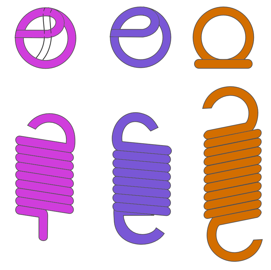
The tensile springs are provided with hooks or loops as shown in the following figure. These loops may be made by turning the whole coil or half of the coil. In a tension spring, a large stress concentration is produced at the loop or other attaching device of the tension spring.

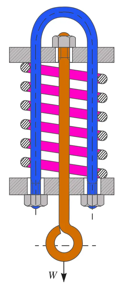
The main disadvantage of a tension spring is the failure of the spring when the wire breaks. A compression spring used for carrying a tensile load is shown in the following figure.

👉 Important Note:
The total number of turns of a tension helical spring must be equal to the number of turns (n) between the points where the loops start plus the equivalent turns for the loops. It has been found experimentally that a half-turn should be added for each loop. Thus for a spring having loops on both ends, the total number of active turns,
n’ = n + 1
This is all about the Material for Helical Springs. Let us know what you think about this article in the comment section below.

Leave a Reply