Fastening is a process of joining two or more machine elements together to work in a function. There will be two types of fastening. Permanent fastening such as welding, riveting and temporary fastening such as screwed joint. Screws are the temporary fasteners. which means the joining of the machine elements can be disassembled whenever it is required without damage to the machine or the fastening with the help of screwed joints. In the previous article, we have discussed the different types Screws available for screwed joints. Let us discuss different Locking devices available for Screwed joints in machine design.
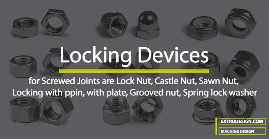
Need of Locking Devices for Screwed Joints
For the static loading, the screwed joints remain tight over the course of time. For the dynamic loading and where the vibrations arouse, these screwed joints may not stay the same tight that they were supposed to. They loosen over time due to different types of loads. If the screwed joint is loosened, then this can be very dangerous, and it may cause damage to the components and result in system failure. This is also very dangerous in terms of the safety of the workers near the system, these loosened nuts will fly and hit the workers near and cause severe damage or even death.
In order to avoid this failure, we have to use the Locking Devices for the Screwed Joints. Let us see the different types of Locking Devices for Bolted Joints.
Different Types of Locking Devices
- Jam nut or Lock Nut
- Castle Nut
- Sawn Nut
- Penn,Ring or Grooved Nut
- Locking with Pin
- Locking with Plate
- Spring Lock Washer
1. Jam Nut or Lock Nut
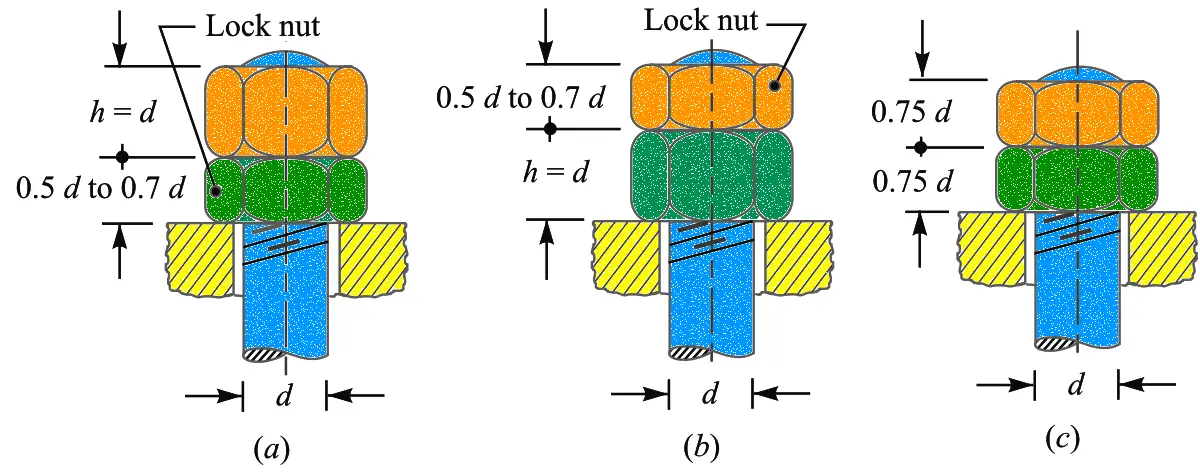
- The most common locking device is a Jam lock or Check nut.
- It has about one-half to the two-thirds thickness of the standard nut.
- The thin lock nut is first tightened down with ordinary force, and then the upper nut (i.e. thicker nut) is tightened down upon it,
- It is shown in the above schematic figure (a) representation of the Lock Nut.
- The upper nut is then held tightly while the lower one is slackened back against it.
- In slackening back the lock nut, a thin spanner is required which is difficult to find in many shops.
- Therefore to overcome this difficulty, a thin nut is placed on the top as shown in above figure (b).
- If the nuts are really tightened down as they should be, the upper nut carries a greater tensile load than the bottom one.
- Therefore, the top nut should be thicker one with a thin nut below it because it is desirable to put whole of the load on the thin nut.
- In order to overcome both the difficulties, both the nuts are made of the same thickness as shown in above figure (c)
2. Castle Nut
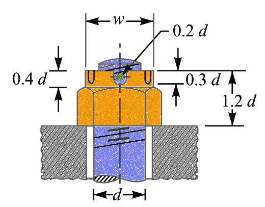
- Castle Nut consists of a hexagonal portion with a cylindrical upper part which is slotted in line with the centre of each face, as shown in the above figure.
- The split pin passes through two slots in the nut and a hole in the bolt, so that a positive lock is obtained unless the pin shears.
- These Castle Locking Nuts are extensively used on jobs subjected to sudden shocks and considerable vibration such as in automobile industry.
3. Sawn Nut
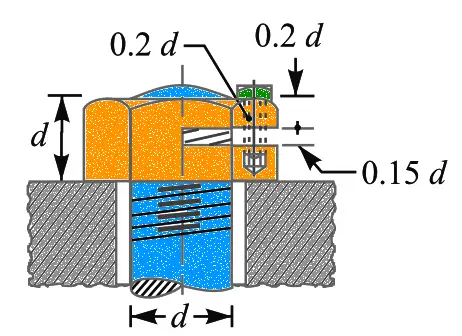
- Sawn Nut has a slot sawed about half way through, as shown in the above figure.
- After the main nut is screwed down, the small screw is tightened which produces more friction between the nut and the bolt.
- This small screw prevents the loosening of nut in the screwed joint from the different types of loading.
4. Penn, Ring or Grooved Nut
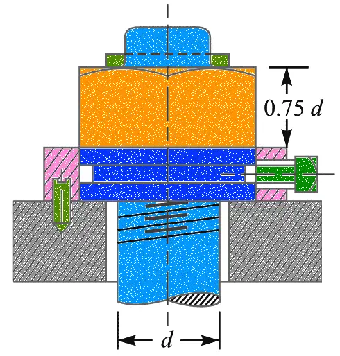
- Grooved Nut has a upper portion hexagonal and a lower part cylindrical as shown in the above figure.
- Grooved Nut is is largely used where bolts pass through connected pieces reasonably near their edges such as in marine type connecting rod ends.
- The bottom portion of the Nut is cylindrical and is recessed to receive the tip of the locking set screw.
- The bolt hole requires counter-boring to receive the cylindrical portion of the nut. In order to prevent bruising of the latter by the case hardened tip of the set screw, it is recessed.
5. Locking With Pin
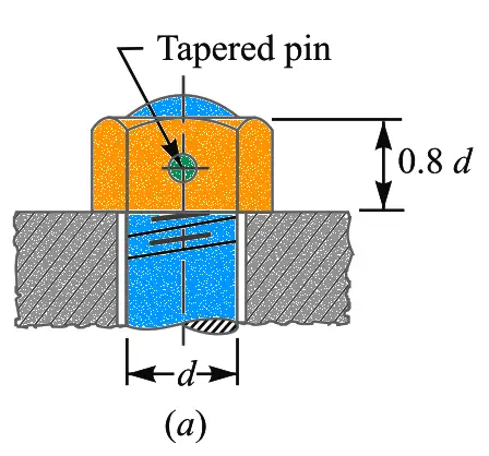
The nuts may be locked by means of a taper pin or cotter pin passing through the middle of the nut as shown in Figure (a).
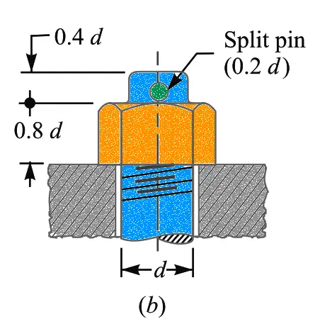
But a split pin is often driven through the bolt end after the nut is screwed on the bolt as shown in the above figure (b).
6 Locking With Plate
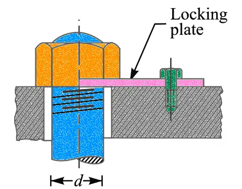
A form of stop plate or locking plate is shown in the above Figure. The nut can be adjusted and subsequently locked through angular intervals of 30° by using these plates. The locking of the Nut can be accomplished by these plates.
7. Spring Lock Washer
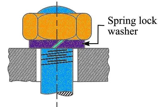
- A spring lock washer is shown in the above Figure.
- As the nut tightens the washer against the piece below, one edge of the washer is caused to dig itself into that piece, thus increasing the resistance so that the nut will not loosen so easily.
- There are many kinds of spring lock washers manufactured, some of which are fairly effective.
Conclusion
These Locking devices make sure the screwed joints safety for the different types of loadings, where vibrations are the unavoidable phenomenon. Let us know what do you think about these above mentioned locking devices in the comment section below.

Leave a Reply