A spring is defined as an elastic body, whose function is to distort when loaded and to recover its original shape when the load is removed. It absorbs or controls energy due to either shock or vibration so it can be used as shock absorbers and vibration dampers. It is also used to apply forces, as in brakes, clutches, and spring-loaded valves. We have already discussed different types of springs in the previous article. Let us discuss the Construction of Leaf Spring and the Length of Leaf Spring Leaves and the stresses in them.

Applications of Springs
The various important applications of springs are as follows:
- To cushion, absorb, or control energy due to either shock or vibration as in car springs, railway buffers, aircraft landing gears, shock absorbers, and vibration dampers.
- To apply forces, as in brakes, clutches, and spring-loaded valves.
- To control motion by maintaining contact between two elements as in cams and followers.
- To measure forces, as in spring balances and engine indicators.
- To store energy, as in watches, toys, etc.
Types of Springs
Though there are many types of springs, the following, according to their shape, are important from the subject point of view.
- Helical springs
- Conical and volute springs
- Torsion springs
- Laminated or Leaf springs
- Disc or Belleville springs
- Special-purpose springs
We have discussed more details for the other springs in a separate article here!
Leaf Spring
The laminated or leaf spring (also known as flat spring or carriage spring) consists of a number of flat plates (known as leaves) of varying lengths held together by means of clamps and bolts. These are mostly used in automobiles. The advantage of leaf spring over helical spring is that the ends of the spring may be guided along a definite path as it deflects to act as a structural member in addition to energy absorbing device. Thus the leaf springs may carry lateral loads, brake torque, driving torque etc., in addition to shocks.
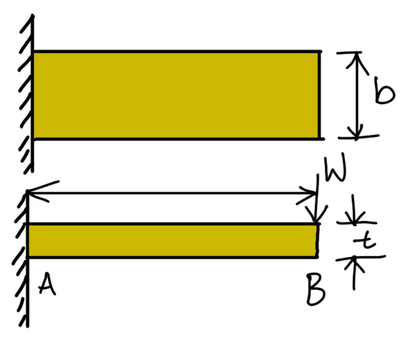
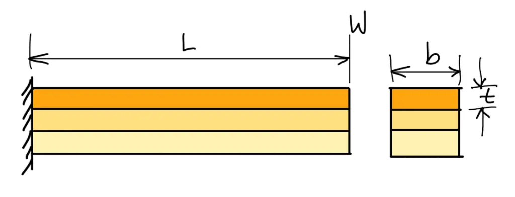
Consider a single plate fixed at one end and loaded at the other end as shown in the following figure. This plate may be used as a flat spring.
Let
t = Thickness of plate
b = Width of plate
L = Length of plate or distance of the load W from the cantilever end
We know that the maximum bending moment at the cantilever end A,
M = W × L
and section modulus,
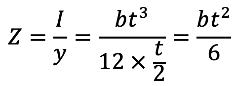
∴ Bending stress in such a spring,
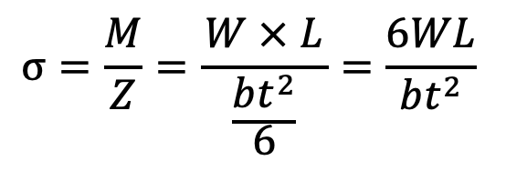
…. Equation (1)
We know that the maximum deflection for a cantilever with concentrated load at the free end is given by

…. Equation (2)
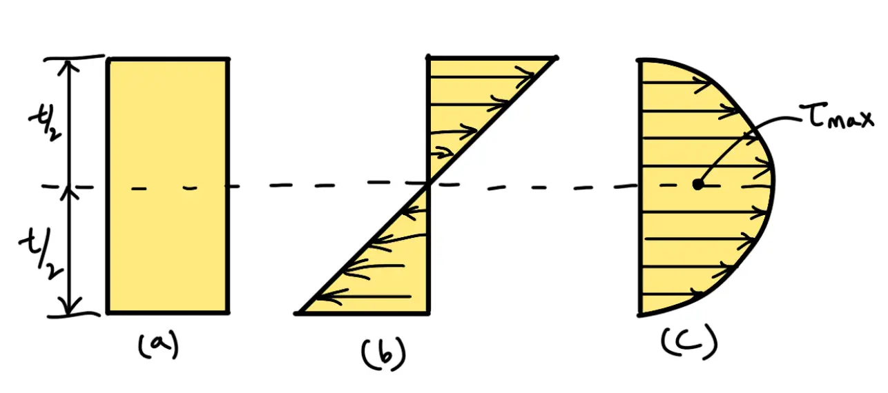
It may be noted that due to bending moment, top fibres will be in tension and the bottom fibres are in compression, but the shear stress is zero at the extreme fibres and maximum at the centre, as shown in the following figure. Hence for analysis, both stresses need not to be taken into account simultaneously. We shall consider the bending stress only.
If the spring is not of cantilever type but it is like a simply supported beam, with length 2L and load 2W in the centre, as shown in the following figure, then
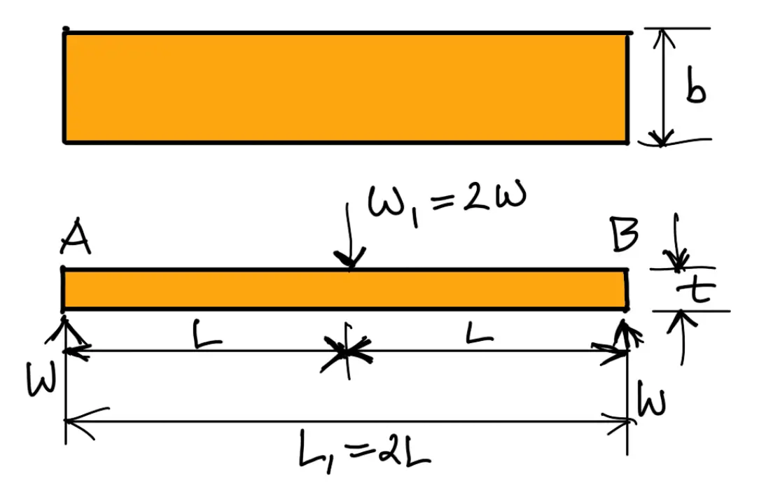
Maximum bending moment in the centre,
M = W × L
Section modulus,
Z = b t 3/ 6
∴ Bending stress,
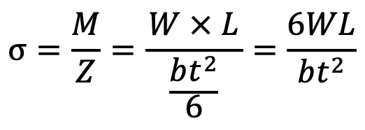
We know that maximum deflection of a simply supported beam loaded in the centre is given by

From above we see that a spring such as automobile spring (semi-elliptical spring) with length 2L and loaded in the centre by a load 2W, may be treated as a double cantilever.
If the plate of cantilever is cut into a series of n strips of width b and these are placed as shown in the following figure, then Bending stress in such a spring, may be written as follows
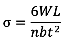
…. Equation (3)
and maximum deflection
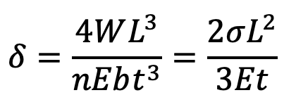
…. Equation (4)
The above relations give the stress and deflection of a leaf spring of uniform cross-section. The stress at such a spring is maximum at the support.
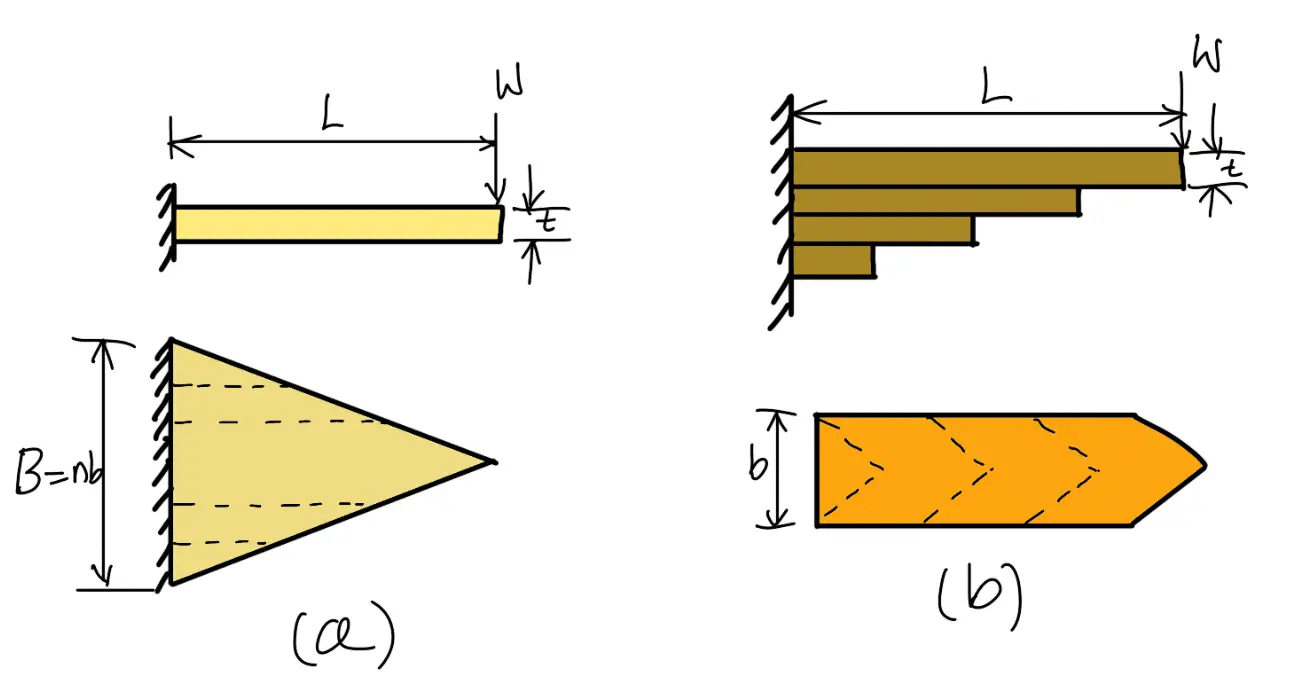
If a triangular plate is used as shown in the following figure (a), the stress will be uniform throughout. If this triangular plate is cut into strips of uniform width and placed one below the other, as shown in the following figuire (b) to form a graduated or laminated leaf spring, then
Bending stress

…. Equation (5)
and the maximum deflection is
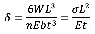
…. Equation (6)
where
n = Number of graduated leaves.
A little consideration will show that by the above arrangement, the spring becomes compact so that the space occupied by the spring is considerably reduced.
When bending stress alone is considered, the graduated leaves may have zero width at the loaded end. But sufficient metal must be provided to support the shear.
Therefore, it becomes necessary to have one or more leaves of uniform cross-section extending clear to the end.
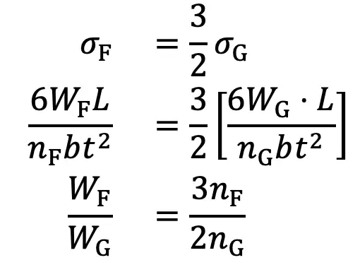
We see from equations (4) and (6) that for the same deflection, the stress in the uniform cross-section leaves (i.e. full length leaves) is 50% greater than in the graduated leaves, assuming that each spring element deflects according to its own elastic curve.
If the suffixes F and G are used to indicate the full length (or uniform cross- section) and graduated leaves, then
…. Equation (7)
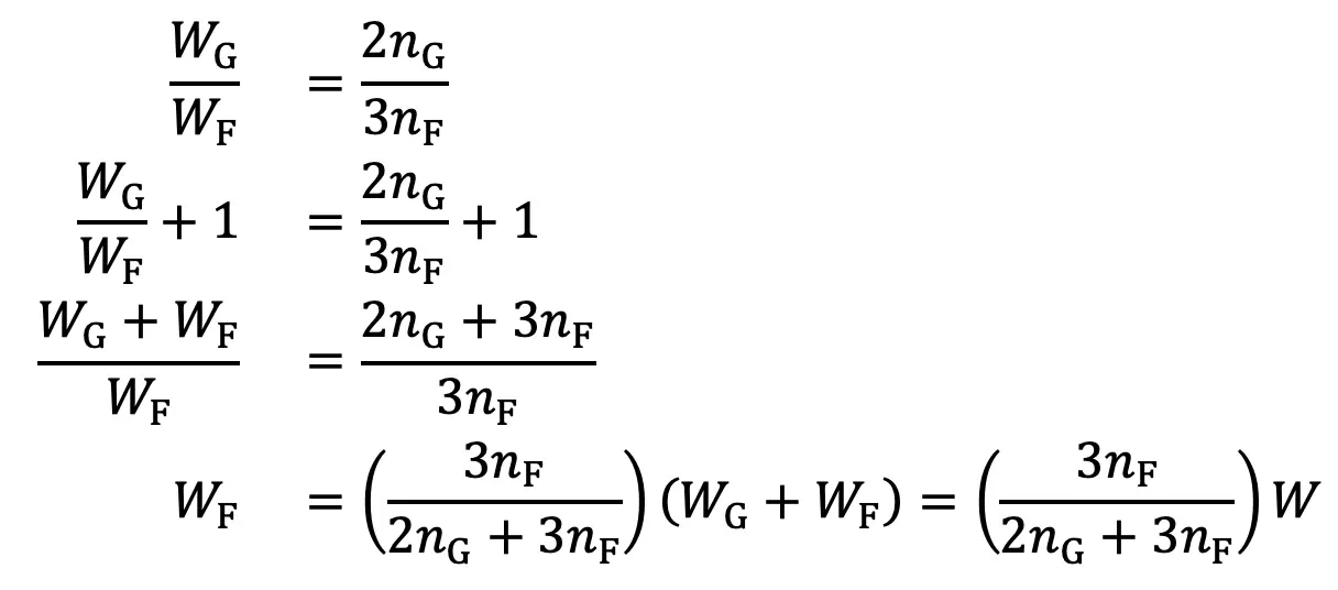
Adding 1 to both sides, we have

…. Equation (8)
W = Total load on the spring = WG + WF
WG = Load taken up by graduated leaves
WF = Load taken up by full length leaves
From equation (7), we may write
…. Equation (9)
∴ Bending stress for full length leaves,
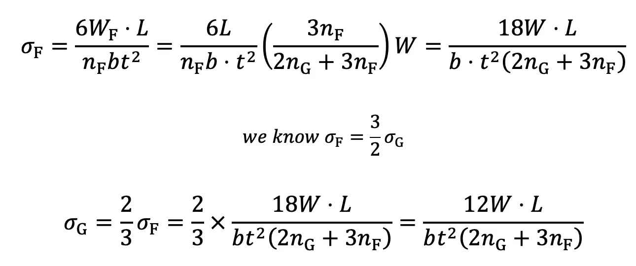
The deflection in full length and graduated leaves is given by equation (4), i.e.

Construction of Leaf Spring
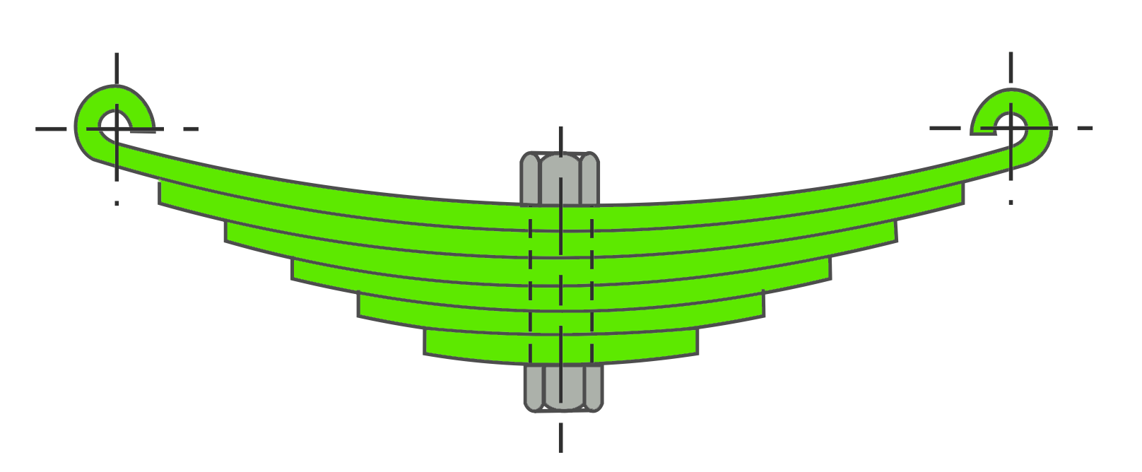
A leaf spring commonly used in automobiles is of semi-elliptical form as shown in the following figure. It is built up of a number of plates (known as leaves). The leaves are usually given an initial curvature or cambered so that they will tend to straighten under the load. The leaves are held together by means of a band shrunk around them at the centre or by a bolt passing through the centre.
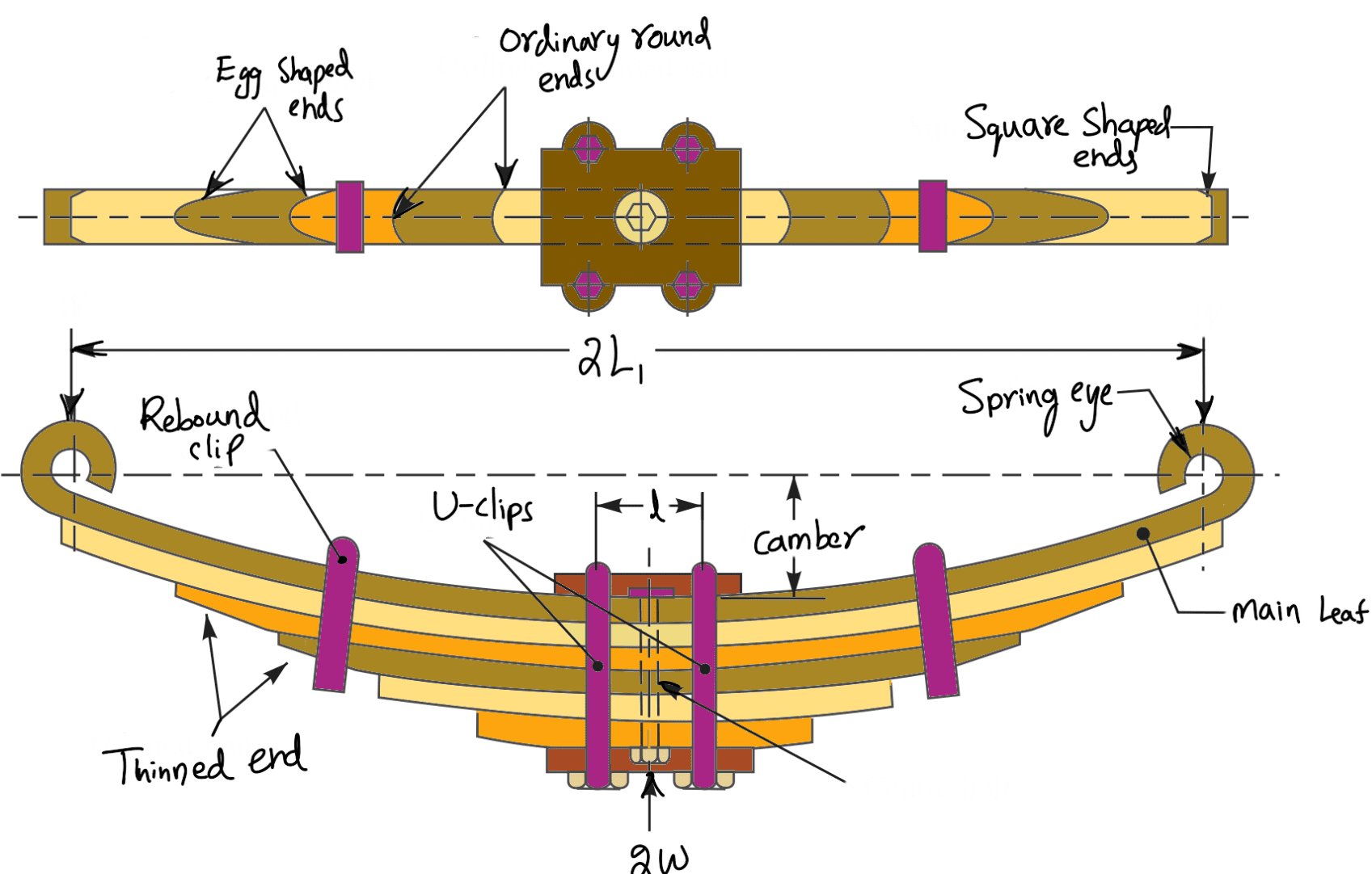
Since the band exerts a stiffening and strengthening effect, therefore the effective length of the spring for bending will be overall length of the spring minus width of band.
In case of a centre bolt, two-third distance between centres of U-bolt should be subtracted from the overall length of the spring in order to find effective length. The spring is clamped to the axle housing by means of U-bolts.
The longest leaf known as main leaf or master leaf has its ends formed in the shape of an eye through which the bolts are passed to secure the spring to its supports. Usually the eyes, through which the spring is attached to the hanger or shackle, are provided with bushings of some anti-friction material such as bronze or rubber.
The other leaves of the spring are known as graduated leaves. In order to prevent digging in the adjacent leaves, the ends of the graduated leaves are trimmed in various forms as shown in the above figure. Since the master leaf has to withstand vertical bending loads as well as loads due to the sideways of the vehicle and twisting, therefore due to the presence of stresses caused by these loads, it is usual to provide two full-length leaves and the rest of graduated leaves as shown in the above schematic diagram.
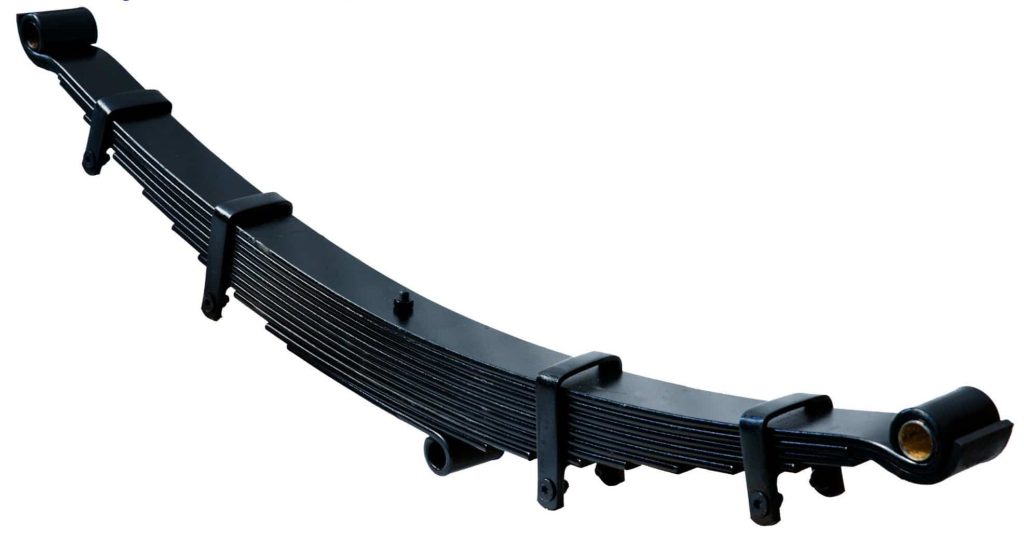
Rebound clips are located at intermediate positions in the length of the spring so that the graduated leaves also share the stresses induced in the full-length leaves when the spring rebounds.
Stress in Leaf Springs (Nipping)
We have already discussed that the stress in the full-length leaves is 50% greater than the stress in the graduated leaves. To utilize the material to the best advantage, all the leaves should be equally stressed.
This condition may be obtained in the following two ways:
- By making the full-length leaves of smaller thickness than the graduated leaves. In this way, the full-length leaves will induce smaller bending stress due to the small distance from the neutral axis to the edge of the leaf.
- By giving a greater radius of curvature to the full-length leaves than graduated leaves, as shown in the following figure, before the leaves are assembled to form a spring. By doing so, a gap or clearance will be left between the leaves. This initial gap, as shown by C in the following figure, is called nip. When the central bolt, holding the various leaves together, is tightened, the full-length leaf will bend back as shown dotted in the following figure, and have an initial stress in a direction opposite to that of the normal load.
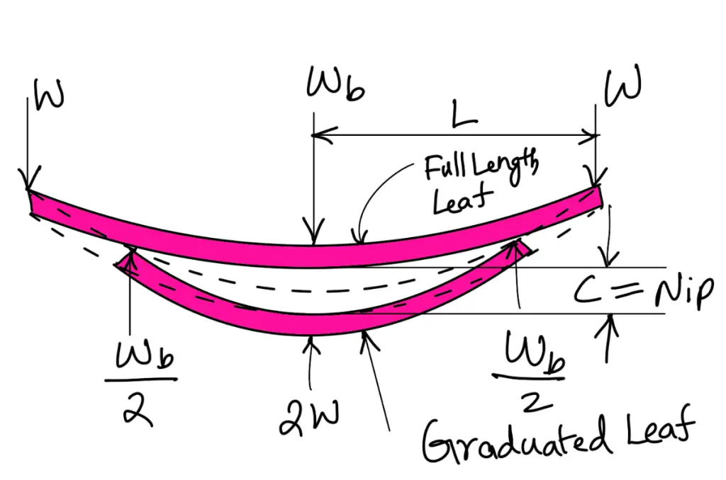
The graduated leaves will have an initial stress in the same direction as that of the normal load. When the load is gradually applied to the spring, the full-length leaf is first relieved of this initial stress and then stressed in the opposite direction. Consequently, the full-length leaf will be stressed less than the graduated leaf. The initial gap between the leaves may be adjusted so that under maximum load conditions the stress in all the leaves is equal, or if desired, the full-length leaves may have the lower stress. This is desirable in automobile springs in which full-length leaves are designed for lower stress because the full-length leaves carry additional loads caused by the swaying of the car, twisting and in some cases due to driving the car through the rear springs. Let us now find the value of the initial gap or nip C.
Consider that under maximum load conditions, the stress in all the leaves is equal. Then at maximum load, the total deflection of the graduated leaves will exceed the deflection of the full-length leaves by an amount equal to the initial gap C. In other words,
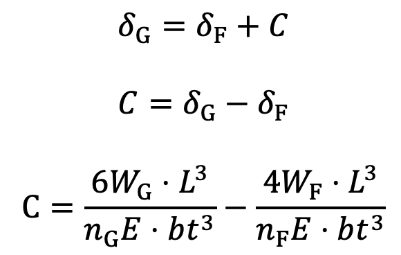
…. Equation (10)
Since the stresses are equal, therefore
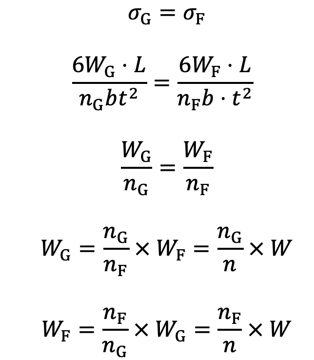
Substituting the values of WG and WF in equation (10), we have

…. Equation (11)
The load on the clip bolts (Wb) required to close the gap is determined by the fact that the gap is equal to the initial deflections of full-length and graduated leaves.
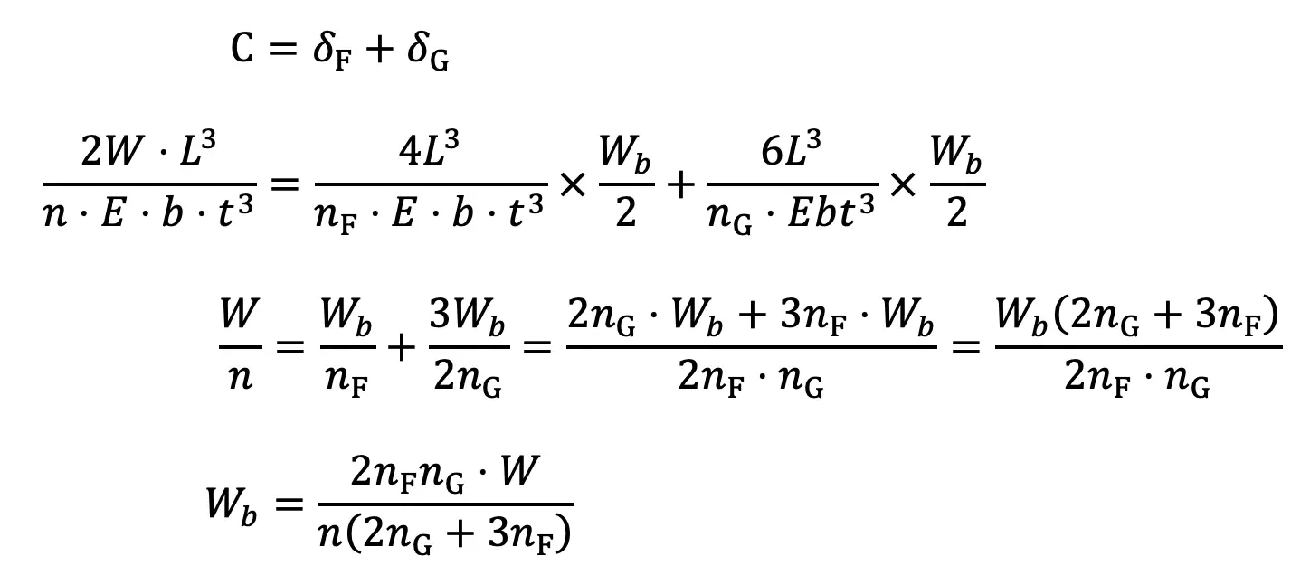
…. Equation (12)
The final stress in spring leaves will be the stress in the full-length leaves due to the applied load minus the initial stress.
∴ Final stress,
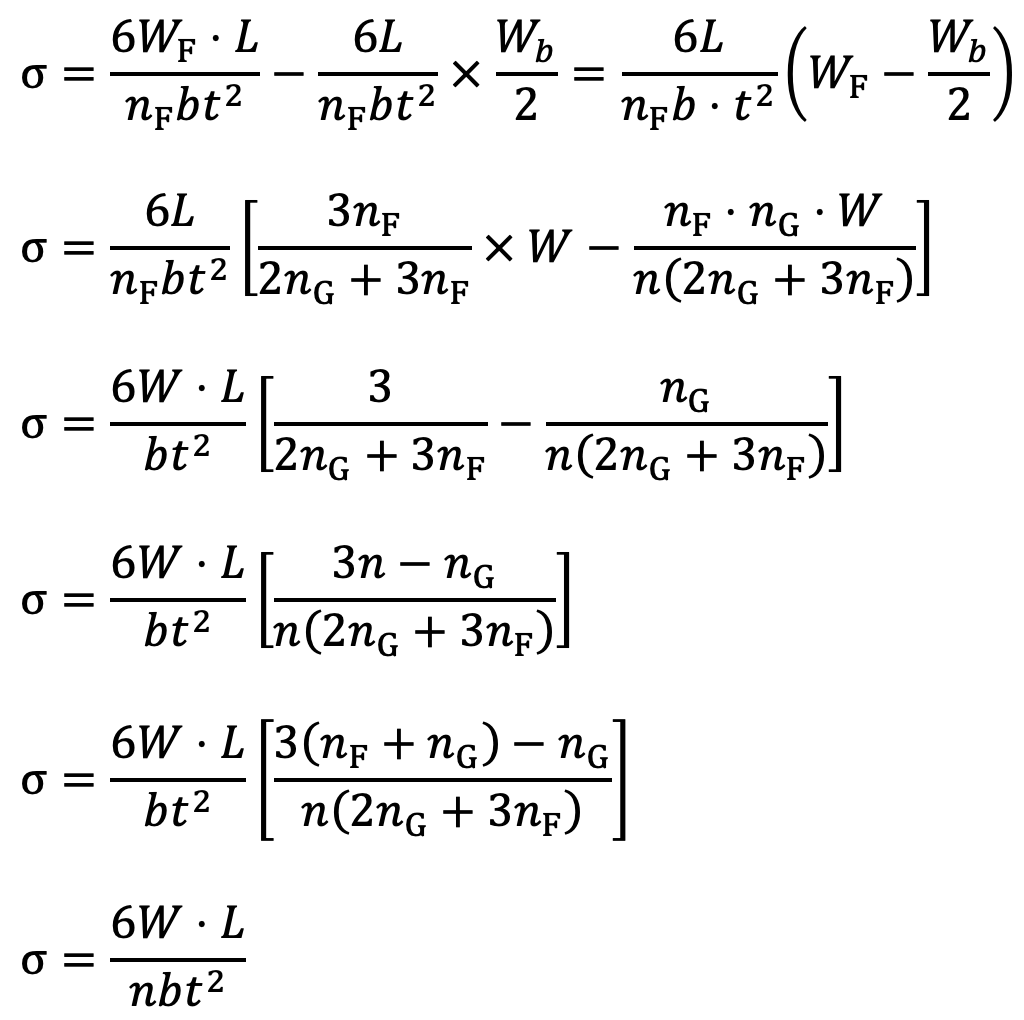
…. Equation (13)
Notes :
- The final stress in the leaves is also equal to the stress in graduated leaves due to the applied load plus the initial stress.
- The deflection in the spring due to the applied load is same as without initial stress.
Length of Leaf Spring Leaves
The length of the leaf spring leaves may be obtained as discussed below:
2L1 = Length of span or overall length of the spring
l = Width of band or distance between centres of U-bolts. It is the ineffective length of the spring
nF = Number of full-length leaves
nG = Number of graduated leaves
n = Total number of leaves = nF + nG
We have already discussed that the effective length of the spring,
When band is used
2L = 2L1 – l
When U-bolts are used
L = 2L1 – (2/3)l
It may be noted that when there is only one full-length leaf (i.e. master leaf only), then the number of leaves to be cut will be n and when there are two full-length leaves (including one master leaf), then the number of leaves to be cut will be (n – 1). If a leaf spring has two full-length leaves, then the length of the leaves is obtained as follows:

The nth leaf will be the master leaf and it is of full length. Since the master leaf has eyes on both sides, therefore
Length of master leaf = 2L1 + π (d+t) × 2
where
d = Inside diameter of eye
t = Thickness of master leaf
The approximate relation between the radius of curvature (R) and the camber (y) of the spring is given by
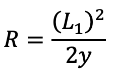
The exact relation is given by
y(2R+y) = (L1)2
where
L1 = Half span of the spring.
The maximum deflection ( δ ) of the spring is equal to the camber (y) of the spring.
Automobile Suspension Leaf Springs Standard Sizes
Following are the standard sizes for the automobile suspension springs:
- Standard nominal widths are 32, 40, 45, 50, 55, 60, 65, 70, 75, 80, 90, 100 and 125 mm.(Dimensions marked* are the preferred widths)
- Standard nominal thicknesses are 3.2, 4.5, 5, 6, 6.5, 7, 7.5, 8, 9, 10, 11, 12, 14 and 16 mm.
- At the eye, the following bore diameters are recommended:19, 20, 22, 23, 25, 27, 28, 30, 32, 35, 38, 50 and 55 mm.
- Dimensions for the center bolts, if employed, shall be as given in the following table.
Table: Dimensions for centre bolts.
| Width of leaves in mm | Dia. of centre bolt in mm | Dia. of head in mm | Length of bolt head in mm |
| Upto and including 65 Above 65 | 8 or 10 12 or 16 | 12 or 15 17 or 20 | 10 or 11 11 |
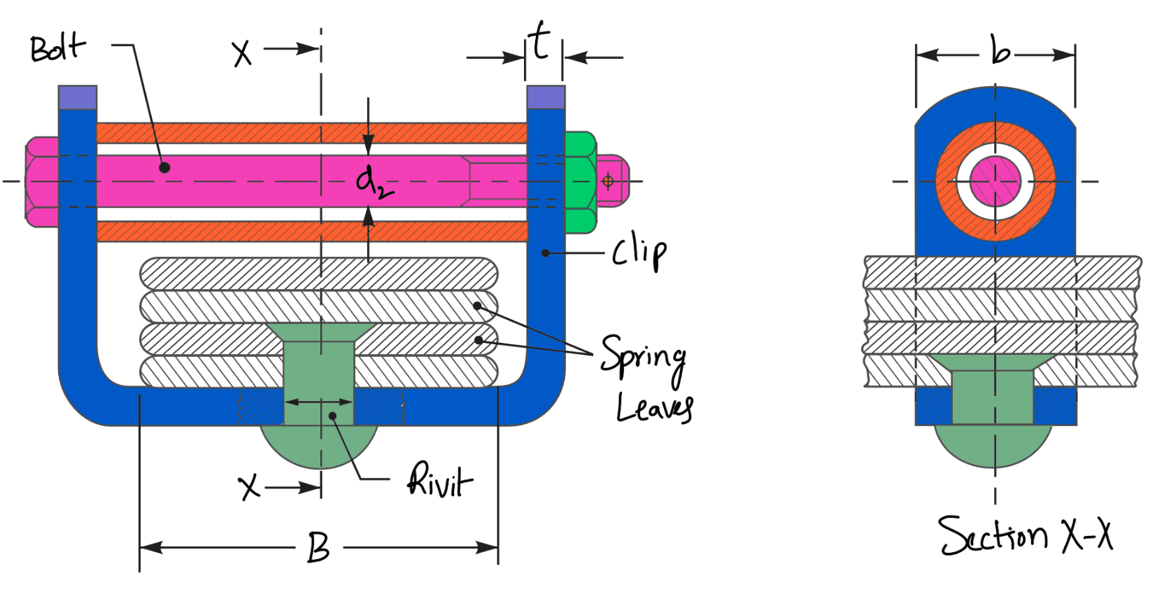
- Minimum clip sections and the corresponding sizes of rivets and bolts used with the clips shall be as given in the following table.
Table: Dimensions of clip, rivet and bolts.
| Spring width (B) in mm | Clip section (b × t) in mm × mm | Dia. of rivet (d1) in mm | Dia. of bolt (d2) in mm |
| Under 50 50, 55 and 60 65, 70, 75 and 80 90, 100 and 125 | 20 × 4 25 × 5 25 × 6 32 × 6 | 68 10 10 | 6 8 8 10 |
👉 Important Notes:
- For springs of width below 65 mm, one rivet of 6, 8 or 10 mm may be used. For springs of width above 65 mm, two rivets of 6 or 8 mm or one rivet of 10 mm may be used.
- For further details, the following Indian Standards may be referred:
(a) IS : 9484 – 1980 (Reaffirmed 1990) on ‘Specification for centre bolts for leaf springs’. (b) IS : 9574 – 1989 (Reaffirmed 1994) on ‘Leaf springs assembly-Clips-Specification.
Materials used for Leaf Springs
The material used for leaf springs is usually a plain carbon steel having 0.90 to 1.0% carbon. The leaves are heat treated after the forming process. The heat treatment of spring steel produces greater strength and therefore greater load capacity, greater range of deflection and better fatigue properties.
According to Indian standards, the recommended materials are :
- For automobiles: 50 Cr 1, 50 Cr 1 V 23, and 55 Si 2 Mn 90 are all used in hardened and tempered states.
- For railroad springs: C 55 (water-hardened), C 75 (oil-hardened), 40 Si 2 Mn 90 (water-hardened) and 55 Si 2 Mn 90 (oil-hardened).
- The physical properties of some of these materials are given in the following table. All values are for oil quenched conditions and for single heat only.
Physical properties of materials commonly used for leaf springs.
| Material | Condition | Ultimate tensile strength (MPa) | Tensile yield strength (MPa) | Brinell hardness number |
| 50 Cr 1 | Hardened and tempered | 1680 – 2200 | 1540 – 1750 | 461 – 601 |
| 50 Cr 1 V 23 | Hardened and tempered | 1900 – 2200 | 1680 – 1890 | 534 – 601 |
| 55 Si 2 Mn 90 | Hardened and tempered | 1820 – 2060 | 1680 – 1920 | 534 – 601 |
Thats it. Thats a full length article on Leaf spring which covers the Construction, Stress, length of Leaves and Materials Used for Leaf springs. Do you still we left any important things related to it?
Let us know in the comment section below. Sure we will add them as soon as we can.

Leave a Reply